Service and Repair Manual August 2021
Fault Inspection Procedure
184 GS
™
-30m • 32m • 30 • 32 • 46 • 55 Part No. 1309020GT
Fault Inspection Procedure
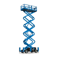
Check the device associated with the faulted circuit
1 Disconnect the faulted device connector.
2 Using a multi-meter, measure resistance between the two
terminals of the faulted device.
3 Resistance should be as follows.
Solenoid Valve, Drive
27.2 Ω
Solenoid Valve, Steer
Ω
Solenoid Valve, Platform Up
Ω
Solenoid Valve, Platform Down
Ω
GCON and PCON Alarm
>1M Ω
1.0 Ω
Motor Controller – Enable
5.7k Ω
Motor Controller – Throttle
5.7k Ω
47 Ω
OK Go to step 2 No Good Replace faulted device
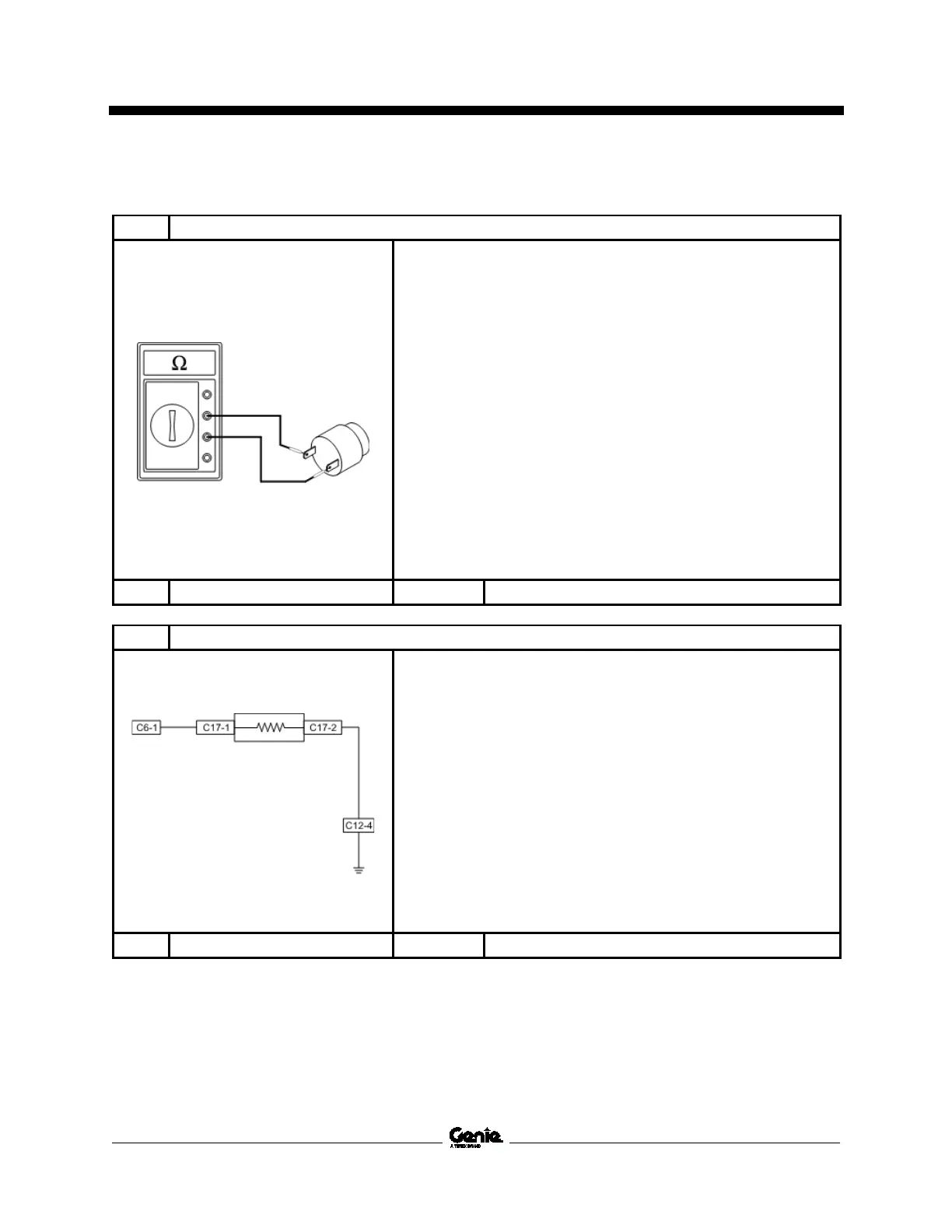
2 Check the harness between the ground controls and the faulted device
1 Disconnect the GCON ECM connectors, J1, J2 and J3.
2 Disconnect the faulted device connector.
3 Check the continuity between the GCON ECM connector
and the signal side of the faulted device.
Result: Resistance should be close to 0 Ω
4 Check the continuity between the return side of faulted
device and system ground.
Result: Resistance should be close to 0 Ω
5 Check resistance between return side and signal side of
the harness plug of faulted device.
Result: Resistance should be 1M Ω or higher.
Replace or repair harness
 Loading...