Service and Repair Manual August 2021
Manifolds
60 GS
™
-30m • 32m • 30 • 32 • 46 • 55 Part No. 1309020GT
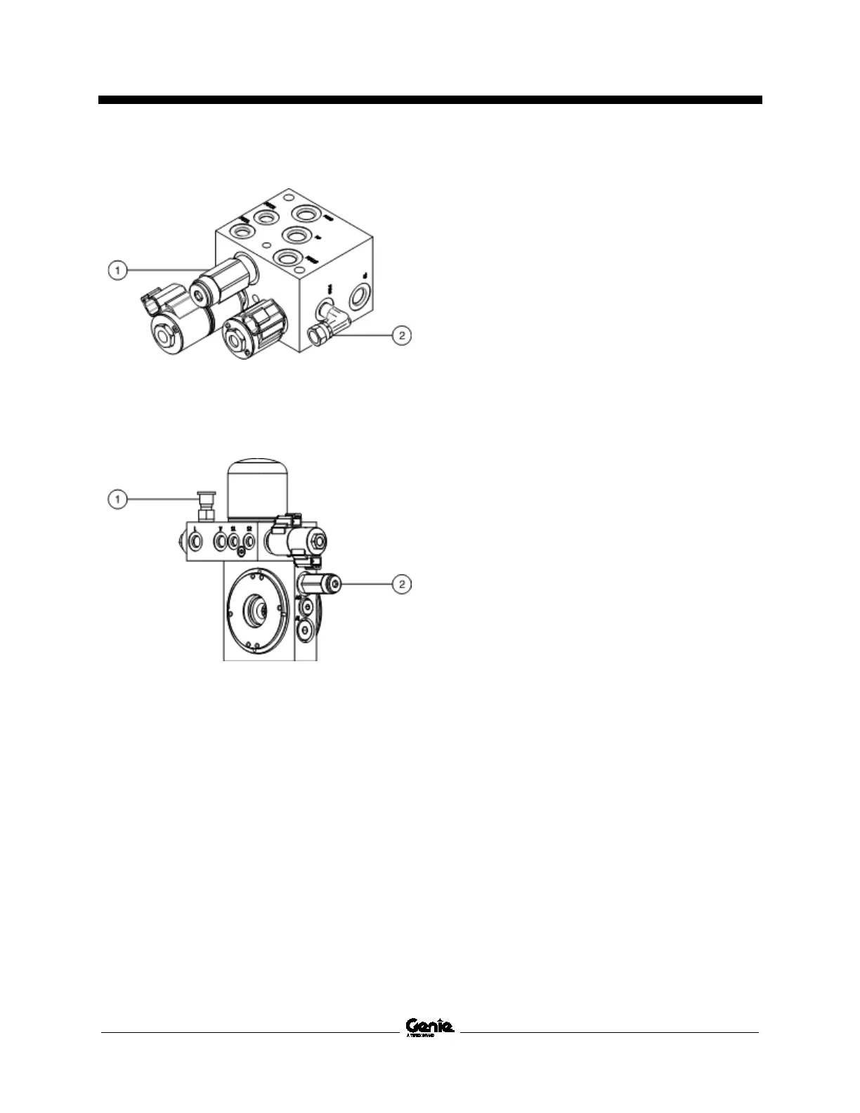
GS-4655
1 system relief valve
2 test port
All other models
1 test port
2 system relief valve
How to A dju st t h e Sys te m Reli e f Val ve - Model s wi t h hy dra ulic driv e
How to Adjust the System Relief
Valve - Models with hydraulic
drive
Note: Perform this test from the ground with the
platform controls. Do not stand in the platform.
1 Connect a 0 to 5000 psi / 0 to 350 bar
pressure gauge to the test port on the function
manifold.
2 Remove the platform controls from the
platform.
3 Turn the key switch to platform controls and
pull out the red Emergency Stop button to the
on position at both ground and platform
controls.
4 Steer the machine fully to the right or left and
hold. Note the pressure reading on the
pressure gauge. Refer to Specifications,
Hydraulic Components Specifications.
5 Turn the machine off. Hold the system relief
valve with a wrench and remove the cap.
6 Adjust the internal hex socket. Turn it
clockwise to increase the pressure or
counterclockwise to decrease the pressure.
 Loading...