www.ti.com
2
SBAU171D–May 2010–Revised January 2016
Submit Documentation Feedback
Copyright © 2010–2016, Texas Instruments Incorporated
ADS1298ECG-FE/ADS1198ECG-FE
5.6 Digital Signals...................................................................................................... 39
5.7 Analog Input Signals.............................................................................................. 39
Appendix A Schematics, BOM, Layout, and ECG Cable Details.......................................................... 41
Appendix B External Optional Hardware...................................................................................... 47
Appendix C Software Installation .............................................................................................. 50
List of Figures
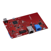
1 ADS1x98ECG-FE Kit........................................................................................................ 5
2 ADS1x98ECG-FE Default Jumper Locations ............................................................................ 6
3 Software Start Screen/About Tab ......................................................................................... 8
4 User Menu - File Item ....................................................................................................... 9
5 User Menu - Help Item...................................................................................................... 9
6 Top Level Controls .......................................................................................................... 9
7 Lead-Off Status Registers Display Window ............................................................................ 10
8 Channel Registers Tab .................................................................................................... 11
9 Internal Reference and Buffer Connections ............................................................................ 12
10 Lead-Off Excitation Options............................................................................................... 13
11 Input Multiplexer for a Single Channel .................................................................................. 13
12 LOFF and RLD Tab........................................................................................................ 14
13 LOFF_STATP and LOFF_STATN Comparators....................................................................... 15
14 GPIO and OTHER Register Tab ......................................................................................... 16
15 Wilson Central and Augmented Lead Routing Diagrams............................................................. 17
16 Device Registers Settings................................................................................................. 18
17 Scope Tool Features....................................................................................................... 19
18 Scope Analysis Tab (Noise Levels for Each Channel Shown)....................................................... 19
19 Zoom Tool Options......................................................................................................... 20
20 Histogram Bins for 12-Lead ECG Signal................................................................................ 21
21 Statistics for the Signal Amplitude of Eight ECG Channels .......................................................... 21
22 FFT Graph of Normal Electrode Configuration......................................................................... 22
23 AC Analysis Parameters: Windowing Options ......................................................................... 22
24 FFT Analysis: Input Short Condition..................................................................................... 23
25 Changing the User-Defined Dynamic Range for Channel 1.......................................................... 23
26 FFT Plot Using Zoom Tool................................................................................................ 24
27 ECG Display Tab Showing LEAD I-III and Augmented Leads ....................................................... 25
28 ECG Signal Zoom Feature for Six Leads ............................................................................... 26
29 ECG Signal Zoom Feature for Lead 1................................................................................... 26
30 Save Tab .................................................................................................................... 28
31 Example of Internal Test Signals Viewed on the ECG Display Tab................................................. 29
32 Internal Temperature Sensor ............................................................................................. 30
33 Eight-Channel Read of Internal Temperature .......................................................................... 30
34 Normal Electrode ECG Connection in ECG Display Tab ............................................................. 31
35 Digitization of PACE Signal Using ADS1298........................................................................... 34
36 ADS1298ECG-FE Front-End Block Diagram........................................................................... 35
37 Fluke Simulator Configuration ............................................................................................ 40
38 Top Component Placement............................................................................................... 44
39 Top Layer ................................................................................................................... 44
40 Bottom Component Placement........................................................................................... 44
41 Bottom Layer................................................................................................................ 44
42 Internal Ground Plane (Layer 2).......................................................................................... 44