Generic Access Profile (GAP)
www.ti.com
28
SWRU271H–October 2010–Revised April 2019
Submit Documentation Feedback
Copyright © 2010–2019, Texas Instruments Incorporated
The Bluetooth Low Energy Protocol Stack
The following describes the possible device states:
• Standby: the initial idle state following reset or when the Bluetooth Low Energy stack is not active
• Advertiser: The device advertises with specific data that signals it can connect to any initiating devices.
This advertisement contains the device address and additional data such as the device name.
• Scanner: When receiving the advertisement, the scanning device sends a request to scan the
advertiser. The advertiser responds with a scan response. This process outlines how the device
discovers other devices. The scanning device reads the advertising device and determines whether or
not they can connect.
• Initiator: When initiating, the initiator must specify a peer device address with which to connect. If the
initiator receives an advertisement that matches the address of the peer device, the initiator will
request to establish a connection with the advertising device. The initiator specifies the initial
connection parameters when the connection is formed.
• Master or Slave: If the device was the advertiser , it becomes a slave after connecting. If the device
was the initiator, it becomes a master after connecting.
5.2.1.1 Connection Parameters
This section describes the connection parameters sent by the initiating device with the connection request.
These parameters can be modified by either device when the connection is established.
These parameters are the following:
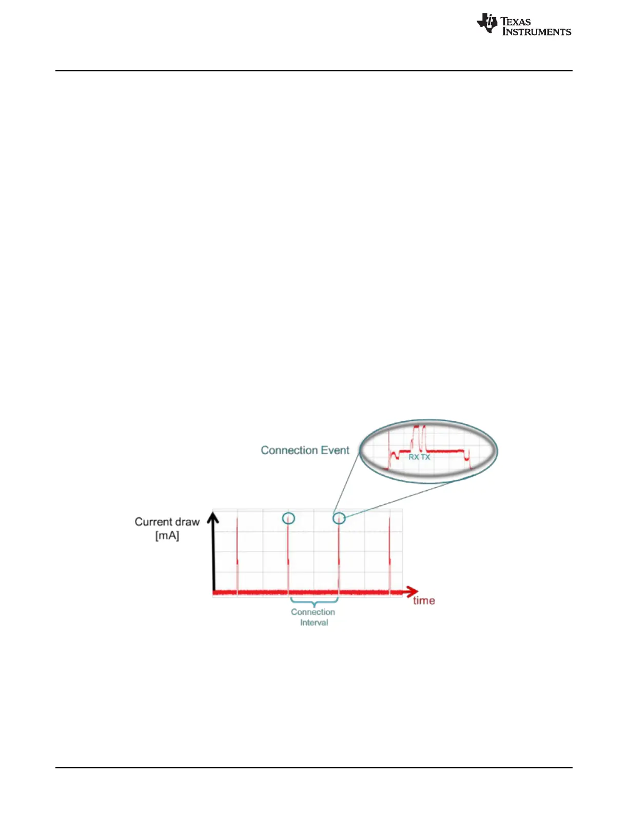
• Connection Interval – Bluetooth Low Energy connections use a frequency-hopping scheme. The
devices send and receive data on a specific channel at a specific time and meet at a new channel
later. The link layer of the Bluetooth Low Energy protocol stack handles the channel switching. This
meeting, where the two devices send and receive data, is a connection event. If there is no application
data sent or received, the devices exchange link layer data to maintain the connection. The connection
interval is the time between two connection events in units of 1.25 ms. The connection interval can
range from a minimum value of 6 (7.5 ms) to a maximum of 3200 (4.0 seconds).
Figure 5-2. Connection Event and Interval
Applications may require different connection intervals. This difference affects the power consumption
of the device. For more detailed information on power consumption, see the Measuring Power
Consumption.