www.ti.com
Hardware Configuration
5
SPRUI25D–June 2015–Revised March 2019
Submit Documentation Feedback
Copyright © 2015–2019, Texas Instruments Incorporated
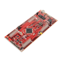
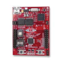
LAUNCHXL-F28377S overview
5 Hardware Configuration
The F28377S LaunchPad provides users with several options on how to configure the board.
5.1 ADC Resolution
While the F28377S device has a 16 bit ADC, this development kit has been designed to use the ADC in
its 12-bit mode. The user can use the ADC in its 16-bit mode by driving the proper differential signals into
the ADC. Performance will not be on par with the data sheet [1] due to the reference circuitry being
designed to match the ADC's 12-bit mode.
5.2 Power Domain
The F28377S LaunchPad has several different power domains to enable JTAG isolation. Jumpers JP1,
JP2, JP4, and JP5 configure where power is passed.
Jumper Power Domain
JP1 Enable 3.3 V from USB (disables isolation)
JP2 Enable GND from USB (disables isolation)
JP4 Connects target MCU 3.3 V to second set of BoosterPack
headers
JP5 Connects target MCU 5 V to second set of BoosterPack headers
5.3 Boot Mode Selection
The LaunchPad's F28377S device includes a boot ROM that performs some basic start-up checks and
allows for the device to boot in many different ways. Most users will either want to perform an emulation
boot or a boot to flash (if they are running the application standalone). S1 has been provided to allow
users to easily configure the pins that the bootROM checks to make this decision. The switches on S1
correspond to:
Switch Function
1 GPIO84
2 GPIO72
3 TRSTn
Keep in mind that the debugger does not connect if the device is not in the emulation boot mode (TRST
switch in the up position). More information about boot mode selection can be found in the Boot ROM
section of the TMS320F2837xS Delfino Microcontrollers Technical Reference Manual (SPRUHX5).
5.4 Connecting a BoosterPack
The F28377S LaunchPad is the perfect experimenter board to start hardware development with the
F2837xS devices. All of the connectors are aligned in a 0.1-in (2.54-mm) grid to allow easy and
inexpensive development of add on boards called BoosterPacks. These satellite boards can access all of
the GPIO and analog signals. The the pin out of the connectors can be found in Section 5.
5.5 Device Migration Path
Applications developed on the LAUNCHXL-F28377S can easily be migrated to any of these lower cost
devices in the F2837xS family:
Part Number Description
TMS320F28377S 32 Bit Real Time Microcontroller, 200 Mhz, 1024KB Flash, 164KB RAM, 16 Bit ADC
TMS320F28376S 32 Bit Real Time Microcontroller, 200 Mhz, 512KB Flash, 132KB RAM, 16 Bit ADC
TMS320F28375S 32 Bit Real Time Microcontroller, 200 Mhz, 1024KB Flash, 164KB RAM, 12 Bit ADC
TMS320F28374S 32 Bit Real Time Microcontroller, 200 Mhz, 512KB Flash, 132KB RAM, 12 Bit ADC

 Loading...


