LMK04821
,
LMK04826
,
LMK04828
SNAS605AR –MARCH 2013–REVISED DECEMBER 2015
www.ti.com
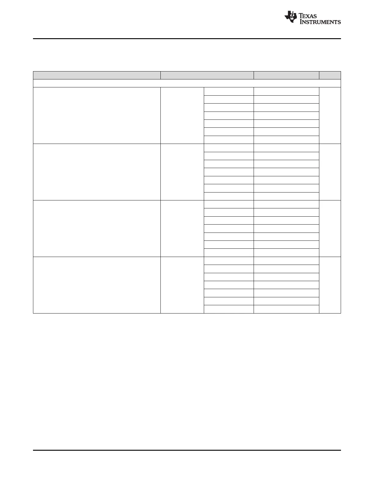
Electrical Characteristics (continued)
(3.15 V < V
CC
< 3.45 V, –40 °C < T
A
< 85 °C and T
PCB
≤ 105 °C. Typical values at V
CC
= 3.3 V, T
A
= 25 °C, at the
Recommended Operating Conditions and are not assured.)
PARAMETER TEST CONDITIONS MIN TYP MAX UNIT
NOISE FLOOR
LVDS –158.2
HSDS 6 mA –160
HSDS 8 mA –161
LMK04821, VCO0, Noise Floor
L(f)
CLKout
245.76 MHz HSDS 10 mA –161.4 dBc/Hz
20 MHz Offset
(13)
LVPECL16 /w 240 Ω –161.6
LVPECL20 /w 240 Ω –162
LVPECL 161.7
LVDS –157.1
HSDS 6 mA –158.3
HSDS 8 mA –159
LMK04821, VCO1, Noise Floor
L(f)
CLKout
245.76 MHz HSDS 10 mA –159.2 dBc/Hz
20 MHz Offset
(13)
LVPECL16 /w 240 Ω –158.8
LVPECL20 /w 240 Ω –158.9
LVPECL –158.8
LVDS –158.1
HSDS 6 mA –159.7
HSDS 8 mA –160.8
LMK04826, VCO0, Noise Floor
L(f)
CLKout
245.76 MHz HSDS 10 mA –161.3 dBc/Hz
20 MHz Offset
(14)
LVPECL16 /w 240 Ω –161.8
LVPECL20 /w 240 Ω –162.0
LCPECL –161.7
LVDS –157.5
HSDS 6 mA –158.9
HSDS 8 mA –159.8
LMK04826, VCO1, Noise Floor
L(f)
CLKout
245.76 MHz HSDS 10 mA –160.3 dBc/Hz
20 MHz Offset
(14)
LVPECL16 /w 240 Ω –160.8
LVPECL20 /w 240 Ω –160.7
LCPECL –160.7
(13) Data collected using a Prodyn BIB-100G balun. Loop filter is C1 = 47 pF, C2 = 3.9 nF, R2 = 620 Ω, C3 = 10 pF, R3 = 200 Ω, C4 = 10
pF, R4 = 200 Ω, PLL1_CP = 450 µA, PLL2_CP = 3.2 mA.. VCO0 PLL2 loop filter bandwidth = 288 kHz, phase margin = 72 degrees.
VCO1 Loop filter loop bandwidth = 221 kHz, phase margin = 70 degrees. CLKoutX_Y_IDL = 1, CLKoutX_Y_ODL = 0.
(14) Data collected using a Prodyn BIB-100G balun. Loop filter for PLL2 is C1 = 47 pF, C2 = 3.9 nF, R2 = 620 Ω, C3 = 10 pF, R3 = 200 Ω,
C4 = 10 pF, R4 = 200 Ω, PLL1_CP = 450 µA, PLL2_CP = 3.2 mA.. VCO0 loop filter bandwidth = 303 kHz, phase margin = 73 degrees.
VCO1 Loop filter loop bandwidth = 151 kHz, phase margin = 64 degrees. CLKoutX_Y_IDL = 1, CLKoutX_Y_ODL = 0.
14 Submit Documentation Feedback Copyright © 2013–2015, Texas Instruments Incorporated
Product Folder Links: LMK04821 LMK04826 LMK04828
 Loading...


