The USB-PD baseband signal is driven on the C_CCn pins with a tri-state driver. The tri-state driver is slew
rate limited to reduce the high frequency components imparted on the cable and to avoid interference with
frequencies used for communication.
9.3.1.2 USB-PD Bi-Phase Marked Coding
The USBP-PD physical layer implemented in the TPS65982 is compliant to the USB-PD Specifications. The
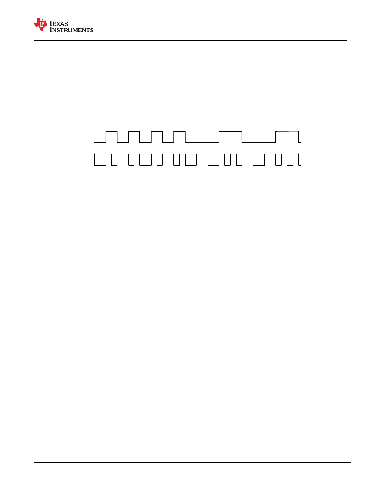
encoding scheme used for the baseband PD signal is a version of Manchester coding called Biphase Mark
Coding (BMC). In this code, there is a transition at the start of every bit time and there is a second transition in
the middle of the bit cell when a 1 is transmitted. This coding scheme is nearly DC balanced with limited disparity
(limited to 1/2 bit over an arbitrary packet, so a very low DC level). Figure 9-4 shows Biphase Mark Coding.
0
1
0
1
0
1
0 0 0 0
1 1
0 0 0
1 1
Data in
BMC
1
Figure 9-4. Biphase Mark Coding Example
The USB PD baseband signal is driven onto the C_CC1 or C_CC2 pins with a tri-state driver. The tri-state driver
is slew rate to limit coupling to D+/D– and to other signal lines in the Type-C fully featured cables. When sending
the USB-PD preamble, the transmitter will start by transmitting a low level. The receiver at the other end will
tolerate the loss of the first edge. The transmitter will terminate the final bit by an edge to ensure the receiver
clocks the final bit of EOP.
9.3.1.3 USB-PD Transmit (TX) and Receive (Rx) Masks
The USB-PD driver meets the defined USB-PD BMC TX masks. Since a BMC coded 1 contains a signal edge
at the beginning and middle of the UI, and the BMC coded 0 contains only an edge at the beginning, the masks
are different for each. The USB-PD receiver meets the defined USB-PD BMC Rx masks. The boundaries of
the Rx outer mask are specified to accommodate a change in signal amplitude because of the ground offset
through the cable. The Rx masks are therefore larger than the boundaries of the TX outer mask. Similarly, the
boundaries of the Rx inner mask are smaller than the boundaries of the TX inner mask. Triangular time masks
are superimposed on the TX outer masks and defined at the signal transitions to require a minimum edge rate
that will have minimal impact on adjacent higher speed lanes. The TX inner mask enforces the maximum limits
on the rise and fall times. Refer to the USB-PD Specifications for more details.
9.3.1.4 USB-PD BMC Transmitter
The TPS65982 transmits and receives USB-PD data over one of the C_CCn pins. The C_CCn pin is also
used to determine the cable orientation (see the Cable Plug and Orientation Detection section) and maintain
cable/device attach detection. Thus, a DC bias will exist on the C_CCn. The transmitter driver will overdrive the
C_CCn DC bias while transmitting, but will return to a Hi-Z state allowing the DC voltage to return to the C_CCn
pin when not transmitting. Figure 9-5 shows the USB-PD BMC TX/Rx driver block diagram.
www.ti.com
TPS65982
SLVSD02E – MARCH 2015 – REVISED AUGUST 2021
Copyright © 2021 Texas Instruments Incorporated
Submit Document Feedback
35
Product Folder Links: TPS65982