BUSPOWERZ Configuration Characteristics). These three voltage ranges configure how the TPS65982 routes
the 5 V present on VBUS to the system in a dead-battery or no-battery scenario.
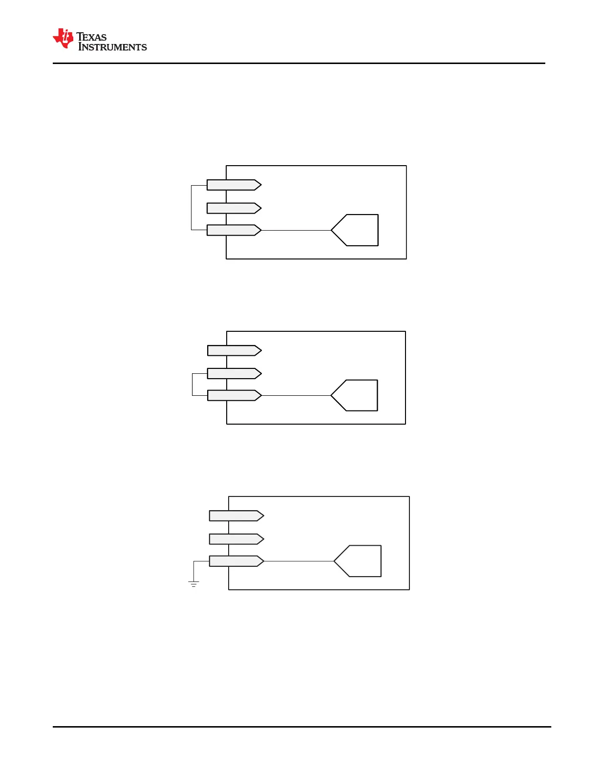
When the voltage on BUSPOWERZ is in the VBPZ_DIS range (when BUSPOWERZ is tied to LDO_3V3 as in
Figure 9-22), this indicates that the TPS65982 will not route the 5 V present on VBUS to the entire system.
In this case, the TPS65982 will load SPI-connected flash memory and execute this application code. This
configuration will disable both the PP_HV and PP_EXT high voltage switches and only use VBUS to power the
TPS65982.
BUSPOWERZ
ADC
LDO_3V3
LDO_1V8D
Figure 9-22. BUSPOWERZ Configured to Disable Power from VBUS
The BUSPOWERZ pin can alternately configure the TPS65982 to power the entire system through the PP_HV
internal load switch when the voltage on BUSPOWERZ is in the VBPZ_HV range (when BUSPOWERZ is tied to
LDO_1V8D as in Figure 9-23).
BUSPOWERZ
ADC
LDO_3V3
LDO_1V8D
Figure 9-23. BUSPOWERZ Configured with PP_HV as Input Power Path
The BUSPOWERZ pin can also alternately configure the TPS65982 to power the entire system through
the PP_EXT external load switch when the voltage on BUSPOWERZ is in the VBPZ_EXT range (when
BUSPOWERZ is tied to GND as in Figure 9-24).
BUSPOWERZ
ADC
LDO_3V3
LDO_1V8D
Figure 9-24. BUSPOWERZ Configured with PP_EXT as Input Power Path
9.3.3.18 Voltage Transitions on VBUS through Port Power Switches
Figure 9-25 shows the waveform for a positive voltage transition. The timing and voltages apply to both a
transition from 0 V to PP_5V0 and a transition from PP_5V0 to PP_HV as well as a transition from PP_5V0 to
an PP_EXT. A transition from PP_HV to PP_EXT is possible and vice versa, but does not necessarily follow the
constraints in Figure 9-25. When a switch is closed to transition the voltage, a maximum slew-rate of SRPOS
occurs on the transition. The voltage ramp will remain monotonic until the voltage reaches VSRCVALID within
the final voltage. The voltage may overshoot the new voltage by VSRCVALID. After time TSTABLE from the
www.ti.com
TPS65982
SLVSD02E – MARCH 2015 – REVISED AUGUST 2021
Copyright © 2021 Texas Instruments Incorporated
Submit Document Feedback
47
Product Folder Links: TPS65982