start of the transition, the voltage will fall to within VSRCNEW of the new voltage. During the time TSTABLE, the
voltage may fall below the new voltage, but will remain within VSRCNEW of this voltage.
TSTABLE
VSRCNEW (max)
Old Voltage
New Voltage
Time
Voltage
SRPOS
VSRCNEW (min)
VSRCVALID (min)
VSRCVALID (max)
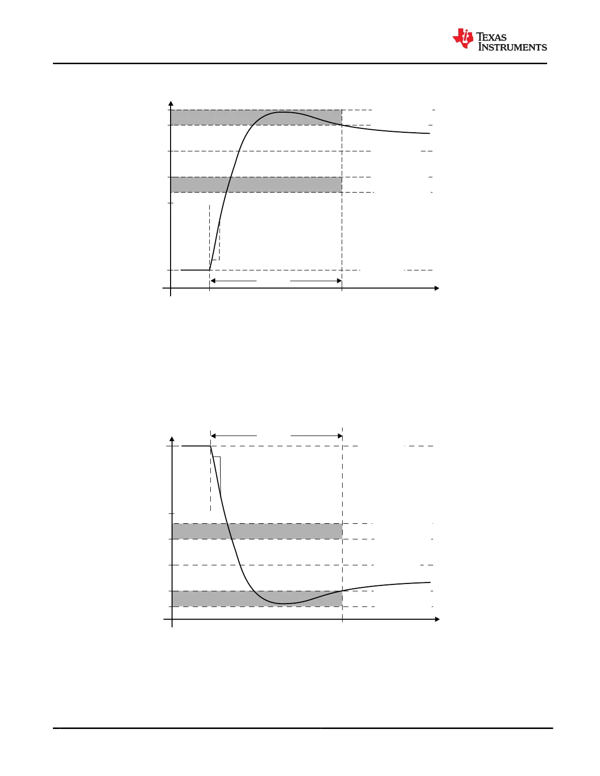
Figure 9-25. Positive Voltage Transition on VBUS
Figure 9-26 shows the waveform for a negative voltage transition. The timing and voltages apply to both a
transition from PP_HV to PP_5V0 and a transition from PP_5V0 to 0V as well as a transition from PP_EXT to
PP_5V0. A transition from PP_HV to PP_EXT is possible and vice versa, but does not necessarily follow the
constraints in Figure 9-26. When a switch is closed to transition the voltage, a maximum slew-rate of SRNEG
occurs on the transition. The voltage ramp will remain monotonic until the voltage reaches TOLTRANUN within
the final voltage. The voltage may overshoot the new voltage by TOLTRANLN. After time TSTABLE from the
start of the transition, the voltage will fall to within VSRCNEW of the new voltage. During the time TSTABLE, the
voltage may fall below the new voltage, but will remain within VSRCNEW of this voltage.
Time
Voltage
TSTABLE
Old Voltage
New Voltage
SRNEG
VSRCVALID (min)
VSRCNEW (min)
VSRCNEW (max)
VSRCVALID (max)
Figure 9-26. Negative Voltage Transition on VBUS
9.3.3.19 HV Transition to PP_RV0 Pull-Down on VBUS
The TPS65982 has an integrated active pulldown on VBUS when transitioning from PP_HV to PP_5V0, shown
in Figure 9-27. When the PP_HV switch is disabled and VBUS > PP_5V0 + VHVDISPD, amplifier turns on a
current source and pulls down on VBUS. The amplifier implements active slew rate control by adjusting the
pulldown current to prevent the slew rate from exceeding specification. When VBUS falls to within VHVDISPD of
TPS65982
SLVSD02E – MARCH 2015 – REVISED AUGUST 2021
www.ti.com
48 Submit Document Feedback
Copyright © 2021 Texas Instruments Incorporated
Product Folder Links: TPS65982