9.3.4.5 Signal Monitoring and Pullup/Pulldown
The TPS65982 has comparators that may be enabled to interrupt the core when a switching event occurs on any
of the port inputs. The input parameters for the detection are listed in the Port Data Multiplexer Signal Monitoring
Pullup and Pulldown Characteristics table. These comparators are disconnected by application code when these
pins are not digital signals but an analog voltage.
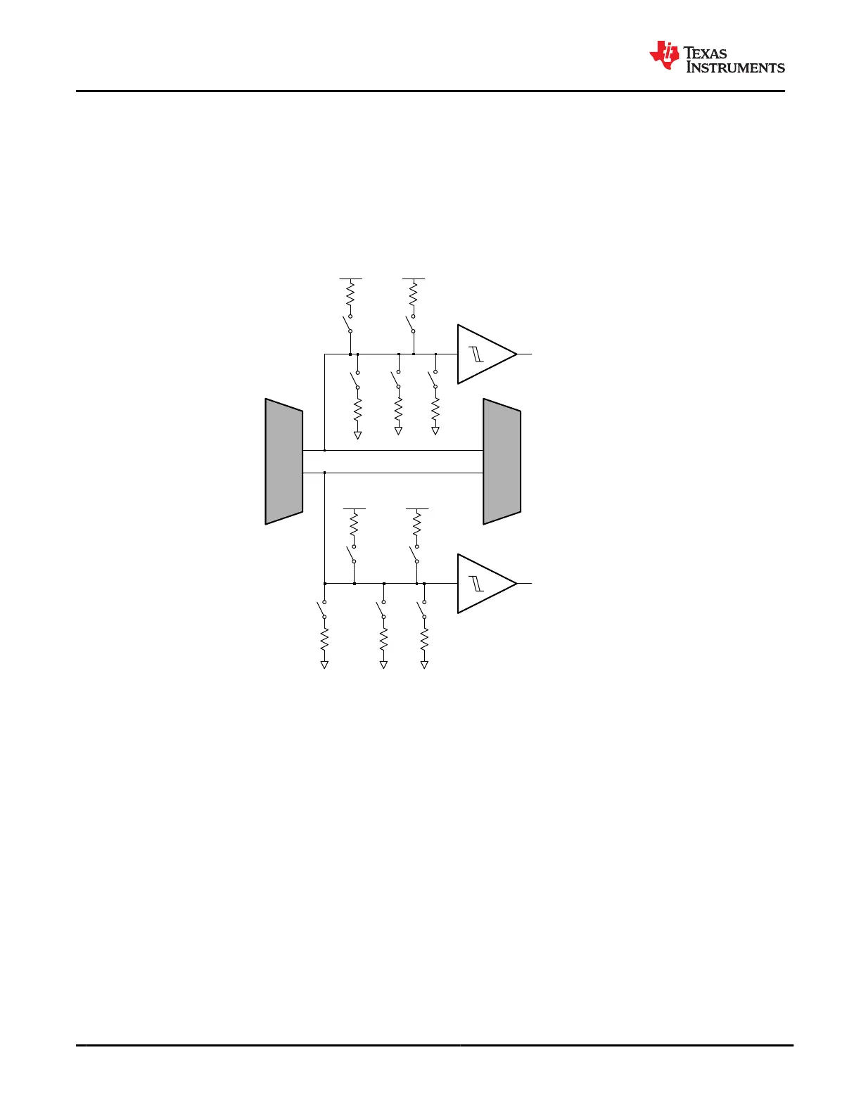
The TPS65982 has pullups and pulldowns between the first and second stage multiplexers of the port switch for
each port output: C_SBU1/2, C_USB_TP/N, C_USB_BP/N. The configurable pullup and pulldown resistances
between each multiplexer are shown in Figure 9-36.
RP5
RP100
LDO_3V3
RP100
RP5
LDO_3V3
RP5
RP100
LDO_3V3
RP100
RP5
LDO_3V3
To Digital Core
To Digital Core
1st Stage
Mux
2nd Stage
Mux
RPD1
RPD1
Figure 9-36. Port Detect and Pullup/Pulldown
9.3.4.6 Port Multiplexer Clamp
Each input to the 2
nd
stage multiplexer is clamped to prevent voltages on the port from exceeding the safe
operating voltage of circuits attached to the system side of the Port Data Multiplexer. Figure 9-37 shows the
simplified clamping circuit. When a path through the 2
nd
stage multiplexer is closed, the clamp is connected
to the one of the port pins (C_USB_TP/N, C_USB_BP/N, C_SBU1/2). When a path through the 2
nd
stage
multiplexer is not closed, then the port pin is not clamped. As the pin voltage rises above the VCLMP_IND
voltage, the clamping circuit activates, and sinks current to ground, preventing the voltage from rising further.
TPS65982
SLVSD02E – MARCH 2015 – REVISED AUGUST 2021
www.ti.com
56 Submit Document Feedback
Copyright © 2021 Texas Instruments Incorporated
Product Folder Links: TPS65982