9.3.4.1 USB Top and Bottom Ports
The Top (C_USB_TP and C_USB_TN) and Bottom (C_USB_BP and C_USB_BN) ports that correspond to the
Type-C top and bottom USB D+/D– pairs are swapped based on the detected cable orientation. The symmetric
pin order shown in Figure 9-34 from the A-side to the B-side allows the pins to connect to equivalent pins on the
opposite side when the cable orientation is reversed.
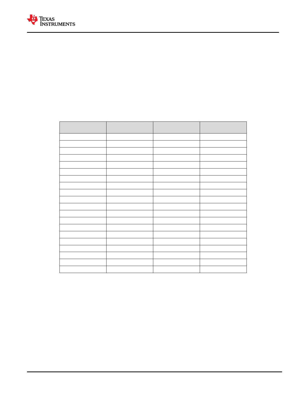
9.3.4.2 Multiplexer Connection Orientation
Table 9-4 shows the multiplexer connection orientation. For the USB D+/D– pair top and bottom port
connections, these connections are fixed. For the SBU port connections, the SBU crossbar multiplexer enables
flipping of the signal pair and the connections shown are for the upside-up orientation. The CORE_UARTn
connections come from a digital crossbar multiplexer that allows the UART_RX/TX, LSX_P2R/R2P, and
GPIO0/1 to be mapped to any of the 1
st
stage multiplexers.
Table 9-4. Data Multiplexer Connections
SYSTEM PIN USB TOP PIN USB BOTTOM PIN
SBU MULTIPLEXER
PIN
USB_RP_P C_USB_TP C_USB_BP
USB_RP_N C_USB_TN C_USB_BN
USB_EP_P C_USB_TP C_USB_BP
USB_EP_N C_USB_TN C_USB_BN
SWD_CLK C_USB_TP C_USB_BP SBU1
SWD_DATA C_USB_TN C_USB_BN SBU2
DEBUG1 C_USB_TP C_USB_BP SBU1
DEBUG2 C_USB_TN C_USB_BN SBU2
DEBUG3 C_USB_TP C_USB_BP SBU1
DEBUG4 C_USB_TN C_USB_BN SBU2
AUX_P C_USB_TP C_USB_BP SBU1
AUX_N C_USB_TN C_USB_BN SBU2
LSX_R2P SBU1
LSX_P2R SBU2
CORE_UART0_TX C_USB_TP
CORE_UART0_RX C_USB_TN
CORE_UART1_TX C_USB_BP
CORE_UART1_RX C_USB_BN
CORE_UART2_TX SBU1
CORE_UART2_RX SBU2
9.3.4.3 Digital Crossbar Multiplexer
The TPS65982 UART paths (UART_RX/TX and LSX_P2R/R2P) and GPIO0/1 all have digital inputs that pass
through a cross-bar multiplexer inside the digital core. Each of these pins is configurable as an input or output of
the cross-bar multiplexer. The digital cross-bar multiplexer then connects to the port data multiplexers as shown
in Figure 9-35. The connections are configurable via firmware. The default state at power-up is to connect a
buffered version of UART_RX to UART_TX providing a bypass through the TPS65982 for daisy chaining during
power on reset.
9.3.4.4 SBU Crossbar Multiplexer
The SBU Crossbar Multiplexer provides pins (C_SBU1 and C_SBU2) for future USB functionality as well as
Alternate Modes. The multiplexer swaps the output pair orientation based on the cable orientation. For more
information on Alternate Modes, refer to the USB PD Specification.
www.ti.com
TPS65982
SLVSD02E – MARCH 2015 – REVISED AUGUST 2021
Copyright © 2021 Texas Instruments Incorporated
Submit Document Feedback
55
Product Folder Links: TPS65982