S
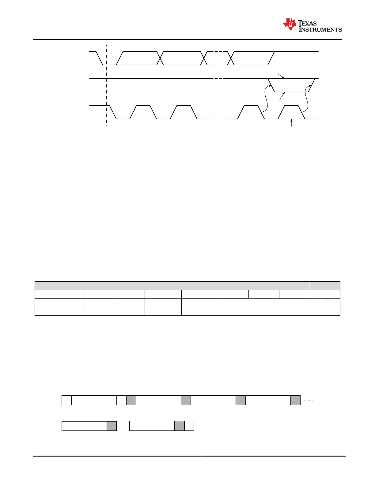
Start
Condition
1 2 8 9
Ack
Nack
Clock Pulse for
Acknowledgement
Data Output
by Transmitter
Data Output
by Receiver
SCL From
Master
Figure 9-63. I
2
C Acknowledgment
9.5.2.2 I
2
C Clock Stretching
The TPS65982 features clock stretching for the I
2
C protocol. The TPS65982 slave I
2
C port may hold the clock
line (SCL) low after receiving (or sending) a byte, indicating that it is not yet ready to process more data. The
master communicating with the slave must not finish the transmission of the current bit and must wait until the
clock line actually goes high. When the slave is clock stretching, the clock line will remain low.
The master must wait until it observes the clock line transitioning high plus an additional minimum time (4 μs for
standard 100 kbps I
2
C) before pulling the clock low again.
Any clock pulse may be stretched but typically it is the interval before or after the acknowledgment bit.
9.5.2.3 I
2
C Address Setting
The boot code sets the hardware configurable unique I
2
C address of the TPS65982 before the port is enabled
to respond to I
2
C transactions. The unique I
2
C address is determined by a combination of the digital level on the
DEBUG_CTL1/DEBUG_CTL2 pins (two bits) and the analog level set by the analog I2C_ADDR strap pin (three
bits) as shown in Table 9-9.
Table 9-9. I
2
C Default Unique Address
Default I
2
C Unique Address for Each Port
Port Number Bit 7 Bit 6 Bit 5 Bit 4 Bit 3 Bit 2 Bit 1 Bit 0
I
2
C Port 1
(1)
0 1 1 1 I2C_ADDR_DECODE[2:0] R/ W
I
2
C Port 2 0 1 DEBUG_CTL2 DEBUG_CTL1 I2C_ADDR_DECODE[2:0] R/ W
(1) I
2
C Port 1 ignores the hardware setting of the DEBUG_CTL1 and DEBUG_CTL2 pins and automatically sets these bits to 1 in Bit 4
and Bit 5 of the address
9.5.2.4 Unique Address Interface
The Unique Address Interface allows for complex interaction between an I
2
C master and a single TPS65982.
The I
2
C Slave sub-address is used to receive or respond to Host Interface protocol commands. Figure 9-64 and
Figure 9-65 show the write and read protocol for the I
2
C slave interface, and a key is included in Figure 9-66 to
explain the terminology used. The key to the protocol diagrams is in the SMBus Specification and is repeated
here in part.
P
S
Unique Address
Wr
Register Number
Byte Count = N
Data Byte 1
A A A A
1 7 1 8 8 81 1 1 1
Data Byte 2
A
8 1
Data Byte N
A
8 1
Figure 9-64. I
2
C Unique Address Write Register Protocol
TPS65982
SLVSD02E – MARCH 2015 – REVISED AUGUST 2021
www.ti.com
78 Submit Document Feedback
Copyright © 2021 Texas Instruments Incorporated
Product Folder Links: TPS65982