Veritas R8 Plus & Excel Installation Manual Installation
INS045-14 9
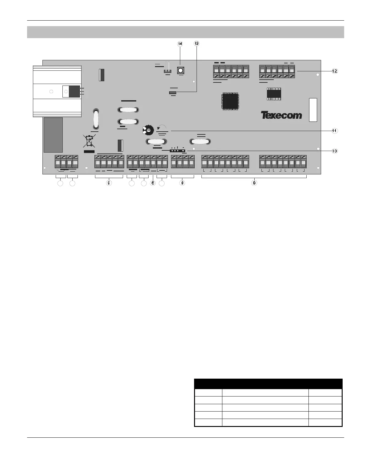
Control Panel PCB Layout
Z1 Z3Z2 Z4
+
TR
-
F1
1 2
Z5 Z7
Z6
Z8
123456
F3
F4
F2
F5
78
4 5
7
SAB
0V
+12V (Unfused)
Zone Lockout
Abor t
Intruder
Set/U ns e t
PA
Fire
Line Monitor
Remote Reset
Duress
Confirmed
1: AC Input
Connected to the 16.5V transformer.
DO NOT CONNECT THE MAINS SUPPLY TO THE AC INPUT
TERMINALS ON THE PCB.
2: Battery Connections
A 12V rechargeable battery must be connected to these terminals in
order to provide continuous system operation in the event of an AC
Mains failure (see page10).
3: External Sounder Connections
These terminals are used for connecting to an external sounder unit
(see page 11 for wiring details).
4: Loudspeaker Connections
These terminals can be used for connecting up to one 16 or two
8loudspeakers (see page 14).
5: Auxiliary 12V Connections
These terminals are for connecting devices that require 12V power
(protected by a 1A fuse F1).
6: SW+ Connections
These terminals are for connecting devices that require 12V power
(protected by a 1A fuse F1).
7: Auxiliary Tamper Connections
These terminals can be used for monitoring the box tamper of
auxiliary devices such as power supplies etc. (see page 14).
8: Keypad Network Connections
These terminals provide connection for the keypads. The ‘+’ and ‘–’
terminals provide power whilst the ‘T’ transmits data and ‘R’
receives data (see page 10).
9: Programmable Zones 1 - 8
These terminals provide the connections for the 8 zones (see page 11).
Each zone is also fully programmable (see page 25).
10: Com1
A portable Engineers keypad or a computer (using a
PC-Com) can be plugged on here to make programming and
testing the system easier.
When using a keypad as an Engineers keypad, the keypad’s
address must all be set to 6 (see page 10).
11: Low Volume Control
This variable resistor controls the volume level of advisory
(entry/exit) tones (turn anticlockwise to increase volume).
12: Communicator Interface
These terminals provide UNFUSED 12V power; a remote reset input,
a line fault input and 8 low current (100mA ‘-ve’ applied) outputs and
would normally be used when connecting a stand-alone
communicator to the control panel (see page 15).
13: Power Indicator
This LED will be ON when AC mains is present on the control panel
and will flash when there is no AC mains present on the control
panel.
14: Box Tamper Switch
This switch provides tamper protection for the main control panel in
case of unauthorised access. To disable the box tamper, fit a
jumper link across the box tamper pins (if fitted).
F1 - F5: Protection Fuses
The following fuses are provided:
Fuse Description Rating
F1 Battery 1 Amp
F2 Bell and Strobe 1 Amp
F3 Auxiliary 12V and Speaker 500mA
F4 Keypad Network 500mA
F5 Power Supply 1.6 Amp

 Loading...