Manual No. 0-5056 3-19 INSTALLATION
3.13 Gas Control Module Installation
The Gas Control Module must be installed in a suitable location where it is easily accessible to the system
operator. The unit must be mounted to a flat horizontal surface. If the Module is mounted to a gantry or to any other
support subject to vibration or motion, the installer must fasten the module to the support securely.
The Module should be located aas far away as possible from the Arc Starter due to electromagnetic interference.
It is acceptable to locate the control cable in the same track as the cables from the Arc Starter.
The Module includes feet which lift the bottom panel off the mounting surface. There are ventilation holes on the
bottom panel; the space between the bottom panel and the mounting surface must remain open for ventilating air
to enter the module. Louvers on the back panel of the module must also remain unblocked, for the free passage
of ventilating air.
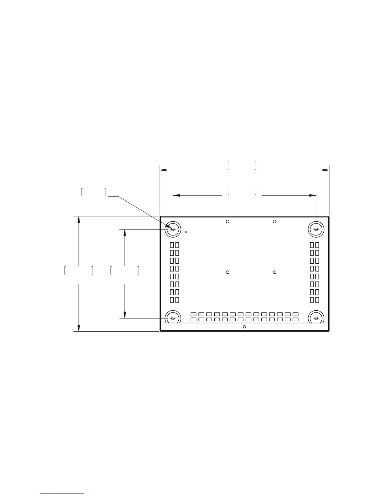
Mounting Dimensions
Art # A-07962
8.50”
215.90mm
0.28”
7.14mm
11.00”
279.40mm
16.18”
410.97mm
13.68”
347.47mm
Gas Box

 Loading...