Manual 0-2971 4-1 OPERATION
SECTION 4:
OPERATION
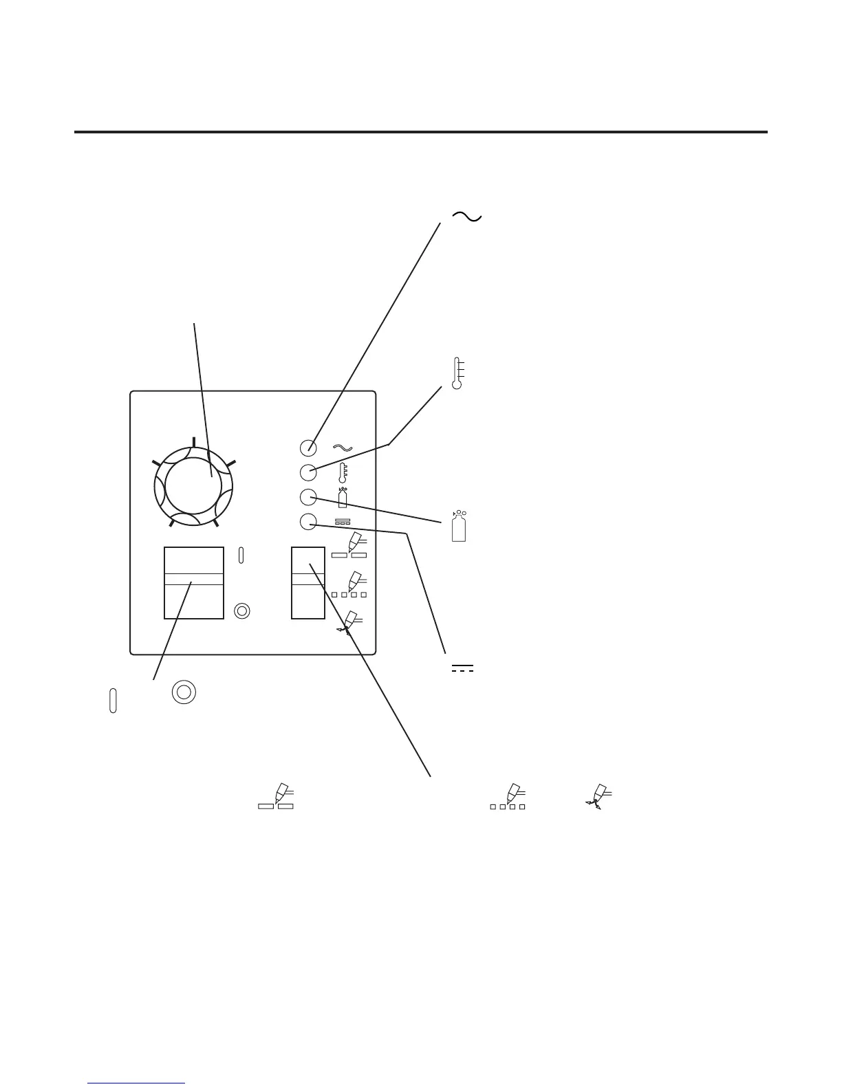
4.01 Front Panel Controls and Indicators
(A) Output Current Control
Sets the desired output current. Output settings up
to 40 Amps may be used for drag cutting (with the
torch tip contacting the workpiece) or standoff cut-
ting.
AC Indicator
Steady light indicates power supply is ready for
operation. Blinking light indicates unit is in pro-
tective interlock mode. Shut unit off, shut off or
disconnect input power, correct the fault, and re-
start the unit. Refer to Section 5 for details.
TEMP Indicator
Indicator is normally OFF. Indicator is ON when
internal temperature exceeds normal limits. Shut
unit OFF; let the unit cool before continuing op-
eration.
GAS Indicator
Indicator is ON when minimum input gas pres-
sure for power supply operation is present. Mini-
mum pressure for power supply operation is not
sufficient for torch operation.
DC Indicator
Indicator is ON when DC output circuit is active.
ON / OFF Switch
Controls input power to the power supply. Up is
ON, down is OFF.
RUN / RAPID AUTO RESTART / SET Switch
RUN (up) position is for general torch operation.
RAPID AUTO RESTART (middle) position is for an uninterrupted restart,
when cutting expanded metal or in gouging or trimming operations.
SET (down) position is for setting gas pressure and purging lines.
20
30
40
25
35
A
A-03742