Do you have a question about the Thermal Dynamics CutMaster 58 and is the answer not in the manual?
Details the meaning of notes, cautions, and warnings used throughout the manual.
Guide on how to effectively read and understand the manual for safe operation.
Information on locating unit, model, and serial numbers for identification purposes.
Instructions for inspecting equipment upon receipt and reporting any shipping damage.
Details technical specifications for the CutMaster 58 power supply, including input and output.
Provides requirements for input voltage, frequency, and cable wiring for the power supply.
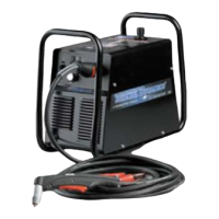
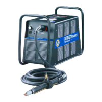
Illustrates and describes key features and components of the power supply unit.
Defines the manual's coverage of Thermal Dynamics torches and cautions against unqualified servicing.
Explains the basic design and operation of plasma torches, including single-gas systems.
Details specifications for torch configurations, leads lengths, parts, and cooling.
Instructions for quickly changing the torch handle assembly from the leads.
Reference to Section 6 for available options and accessories for the plasma system.
Explains the principles of plasma gas flow and its role in cutting and gouging processes.
Steps for unpacking the equipment, checking for damage, and recording identification numbers.
Safety precautions and methods for safely lifting and transporting the power supply unit.
Procedure for accessing the contactor cover to make input power connection changes.
Instructions for connecting primary input power in single-phase configuration.
Instructions for connecting primary input power in three-phase configuration.
Guidance on connecting the compressed air or high pressure gas supply to the unit.
Procedure for connecting the torch lead to the power supply, including safety warnings.
Steps for mounting and aligning the mechanical torch for optimal cutting performance.
Detailed explanation of all controls, indicators, and features on the power supply front panel.
Steps to prepare the system for operation, including torch parts, connections, and air source.
Guide on selecting appropriate torch parts based on the type of cutting or gouging operation.
Factors influencing cut quality, such as standoff, alignment, speed, and gas pressure.
Provides information on cut surface characteristics, bevel angle, dross, kerf width, and cutting direction.
Detailed instructions for operating the hand torch for standoff cutting, edge starting, and piercing.
Parameters and techniques for performing plasma gouging operations, including travel speed and lead angle.
Instructions for operating the torch in mechanized cutting applications, including travel speed and piercing.
Lists consumable parts for manual torch cutting, including common errors and part numbers.
Tables providing recommended cutting speeds for various material thicknesses with an exposed tip torch.
Tables providing recommended cutting speeds for various material thicknesses with a shielded tip torch.
Lists catalog numbers and corresponding U.S. and Foreign patents for plasma cutting torch parts.
Provides a schedule for general maintenance checks for the power supply system.
Details recommended maintenance checks based on operating hours or frequency.
Lists common problems, their symptoms, possible causes, and recommended solutions.
Explains the fault indicator lights and their corresponding error codes and meanings.
A guide to diagnose and resolve common operational problems with the plasma cutting system.
Procedures for basic replacement of parts such as covers and filter elements.
Guidelines for cleaning the torch, lubricating O-rings, and general upkeep.
Instructions for inspecting, cleaning, and replacing consumable parts of the plasma torch.
Overview of the parts list breakdown and how to order components.
Instructions on how to order replacement parts, including necessary information.
Details of the power supply replacement unit and its included components.
List of replacement parts available for the power supply unit.
Catalog of optional items and accessories available for the plasma cutting system.
List of replacement parts specifically for the hand torch assembly.
Catalog of consumable parts for the SL60 torch, including part numbers and common errors.
Catalog of consumable parts for the SL100 torch, detailing tips and shield caps.
Explains symbols and provides context for data tag information related to power supply specifications.
Diagram showing pin assignments for the ATC male and female connectors on a hand torch.
Diagram showing pin assignments for mechanized torch ATC connectors and remote pendant.
Wiring diagram illustrating the connection between a hand torch, power supply, and ATC connector.
Wiring diagram for mechanized torch, showing connections to power supply and remote pendant.
Lists various test points on the PCB1 Main PCB Assembly for diagnostic purposes.
Lists various test points on the PCB1 Main PCB Assembly for diagnostic purposes.
Records the release date and revision level of the manual.
| Brand | Thermal Dynamics |
|---|---|
| Model | CutMaster 58 |
| Category | Welding System |
| Language | English |


