CUTMASTER 58
Manual 0-5544 INSTALLATION
3-1
SECTION 3 SYSTEM:
INSTALLATION
3.01 Unpacking
1. Use the packing lists to identify and account for
each item.
2. Inspect each item for possible shipping damage.
If damage is evident, contact your distributor and
/ or shipping company before proceeding with
the installation.
3. Record Power Supply and Torch model and serial
numbers, purchase date and vendor name, in the
information block at the front of this manual.
3.02 Lifting Options
The Power Supply includes a handle for hand lifting
only. Be sure unit is lifted and transported safely and
securely.
WARNING
Do not touch live electrical parts.
Disconnect input power cord be-
fore moving unit.
FALLING EQUIPMENT can cause
serious personal injury and can
damage equipment.
HANDLES are not for mechanical
lifting.
• Only persons of adequate physical strength should
lift the unit.
• Lift unit by the handles, using two hands. Do not
use straps for lifting.
• Use optional cart or similar device of adequate
capacity to move unit.
• Place unit on a proper skid and secure in place
before transporting with a fork lift or other vehicle.
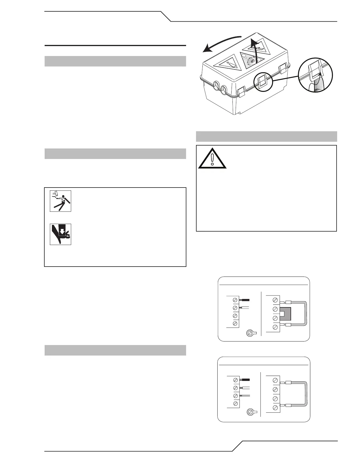
3.03 Opening the Contactor Cover
The input power cord is connected to the main contactor,
the contactor is located inside a box with a snap on cover.
The cover is held in place with two or more snap lock
tabs. To remove the cover release the front latch and tilt
the cover up about ½ inch. Then squeeze both sides of
the cover and lift it straight up. See the Primary Input
Power Connections section for the necessary changes to
the Contactor. Remember to replace the Contactor Cover
when the changes are complete.
1
2
2
1
Contactor cover
3.04 Primary Input Power Connections
!
CAUTION
Check your power source for correct volt-
age before plugging in or connecting the
unit. Check the Voltage Selector at the rear
of the unit for correct setting before plug-
ging in or connecting the unit. The primary
power source, fuse, and any extension
cords used must conform to local electrical
code and the recommended circuit protec-
tion and wiring requirements as specified
in Section 2.
Most units are shipped from the factory with a 230Volt
input power cable wired to the input contactor in the
single - phase configuration. The following illustrations
and directions are for changing that configuration to a
different voltage and or to three - phase operation or
back again if a change had already been made.
Single-Phase (1ø) and Jumper Settings
L1
L2
L3
L4
Jumper L1 -L4
Jumper
L2-L3
L1
L2
L3
GND
L4
Single Phase Input Power Wiring
Three-Phase (3ø) and Jumper Settings
L1
L2
L3
L4
Jumper L1 -L4
L1
L2
L3
GND
L4
Store copper jumper in spare parts box
Three Phase Input Power Wiring