EasyManua.ls Logo

Thermal Dynamics 81 CUTMASTER Service Manual

Thermal Dynamics 81 CUTMASTER
88 pages
To Next Page IconTo Next Page
Page #1 background imageLoading...
Page #1 background image
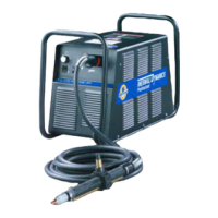
PLASMA CUTTING SYSTEM
81
CUTMASTER
Rev. AC.01 Date: April 13, 2007 Manual # 0-2957
Operating Features:
A-04517
Service Manual

Table of Contents

Questions and Answers:

Thermal Dynamics 81 CUTMASTER Specifications

General IconGeneral
BrandThermal Dynamics
Model81 CUTMASTER
CategoryWelding System
LanguageEnglish

Summary

SECTION 1: GENERAL INFORMATION

1.02 Safety Precautions and Hazards

Covers gases, fumes, electric shock, fire, explosion, noise, and arc rays hazards.

1.08 Statement of Warranty

Outlines limited warranty terms, conditions, and exclusions for the product.

SECTION 3: DESCRIPTION

3.02 Power Supply Specifications

Details electrical and operating specifications for the power supply.

SECTION 4: TROUBLESHOOTING

4.03 System Theory

Explains the logic board functions and system operation principles.

4.04 Common Operating Problems

Describes typical issues like dross, penetration, and arc problems with causes.

4.05 Troubleshooting Guide - General Information

Covers advanced troubleshooting, disassembly, and how to use the guide.

4.06 Circuit Fault Isolation

Guides fault isolation using controls, indicators, and setup conditions.

4.07 Main Input and Internal Power Problems

Addresses issues related to main input power and internal power circuits.

4.08 Pilot Arc Problems

Details troubleshooting for pilot arc failures and symptoms.

4.09 Main Arc Problems

Lists common problems and solutions for the main cutting arc.

4.10 Test Procedures

Outlines various tests for components and circuits.

SECTION 5: REPLACEMENT PROCEDURES

APPENDIX 1: INPUT WIRING REQUIREMENTS

APPENDIX 2: SEQUENCE OF OPERATION (BLOCK DIAGRAM)

APPENDIX 5A: MAIN PC BOARD WIRING LAYOUT - 208/230-Volt Units

APPENDIX 5B: MAIN PC BOARD WIRING LAYOUT - 400-Volt, 415-Volt 460-Volt, and 600-Volt Units

APPENDIX 10: OUTPUT BOARD WIRING DIAGRAM

APPENDIX 14: TORCH PIN-OUT DIAGRAMS

APPENDIX 15: TORCH CONNECTION DIAGRAMS

APPENDIX 16A: SYSTEM SCHEMATIC, 208/230-Volt Units

APPENDIX 16B: SYSTEM SCHEMATIC, 400-Volt, 415-Volt and 460-Volt Units

APPENDIX 16C: SYSTEM SCHEMATIC, 600-Volt Units

Related product manuals