Manual 0-2957 A-7 APPENDIX
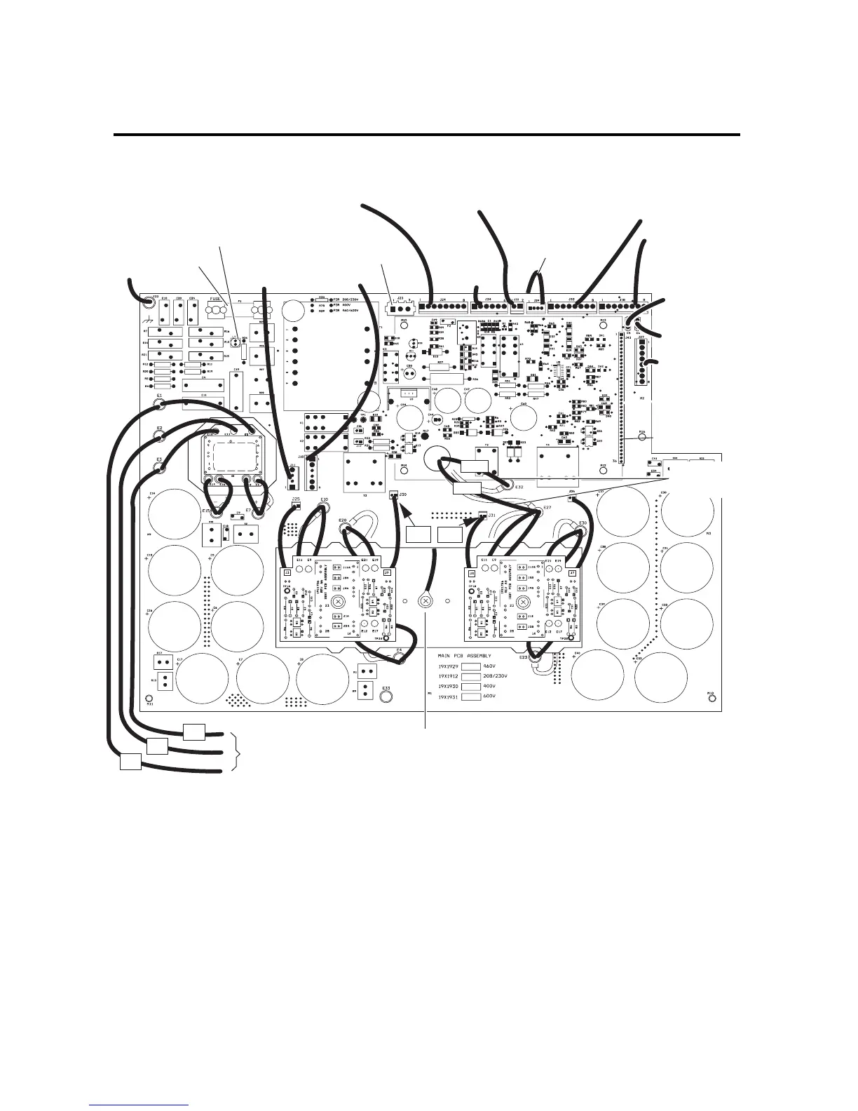
APPENDIX 5B: MAIN PC BOARD WIRING LAYOUT -
400-Volt, 415-Volt 460-Volt, and 600-Volt Units
INPUT
DIODE
Art # A-03653
#2
#3
#1
To Input
Contactor
To Chassis
Ground
To To r c h
Connector
To Fans
To Main
Input Contactor
Te s t
Connector
Heat Sink
Temp Sensor
To Inductor Temp Sensor
To Press Switch/Solenoid/Contactor
Fuse
Secondary
Transformer
To Main
Transformer
To Logic Board
via Connector
To Power Output
Board
To On/Off and
Run/Rapid Restart
Set Switches
To Heat Sink
Temp Sensor
To Auto Interface
Board J1-5*
To Auto Interface
Board J1-6*
* Automation Interface Board is not installed in all units.
To POT/LED PCB
(or to
Optional Remote
Current Control )*
* If installed in conjuction
with Automation Interface PC Board
#32
#27
LT1
J30
J31