Manual 0-2957 4-5 TROUBLESHOOTING
D. Pilot Arc Test
1. Activate the torch (press torch switch on the handle,
send START signal from CNC Control, or press the
torch switch on the Remote Pendant) to establish a
pilot arc and note the following:
• Gas flows
• Preflow delay (approximately two seconds) then DC
indicator turns ON
• Pilot arc is established
This completes the Pilot Arc Test. If the above are all cor-
rect then proceed to paragraph 'E'. If the unit does not
function properly, then note the symptom and proceed
to Subsection 4.08, Pilot Arc Problems.
E. Main Arc Test
Make sure the work cable is firmly connected to the work-
piece. Activate the torch (press torch switch on the handle,
send START signal from CNC Control or press the torch
switch on the Remote Pendant) to establish a pilot arc.
Bring the torch to within 1/8"-3/8" (3-10 mm) of the work-
piece to establish the main cutting arc, and note the fol-
lowing:
• Main cutting arc transfers to workpiece.
This completes the Main Arc Test. If the above are all
correct then the equipment should be operating properly.
If problems still persist then contact Technical Services.
If the torch does not function as noted then note the symp-
tom and proceed to Subsection 4.09, Main Arc Problems.
4.07 Main Input and Internal
Power Problems
A. Opening Power Supply Enclosure
The cover of the Power Supply must be removed for ac-
cess to input power connections and test points.
WARNING
Disconnect primary power at the source before as-
sembling or disassembling the Power Supply, torch
parts, or torch and leads assemblies.
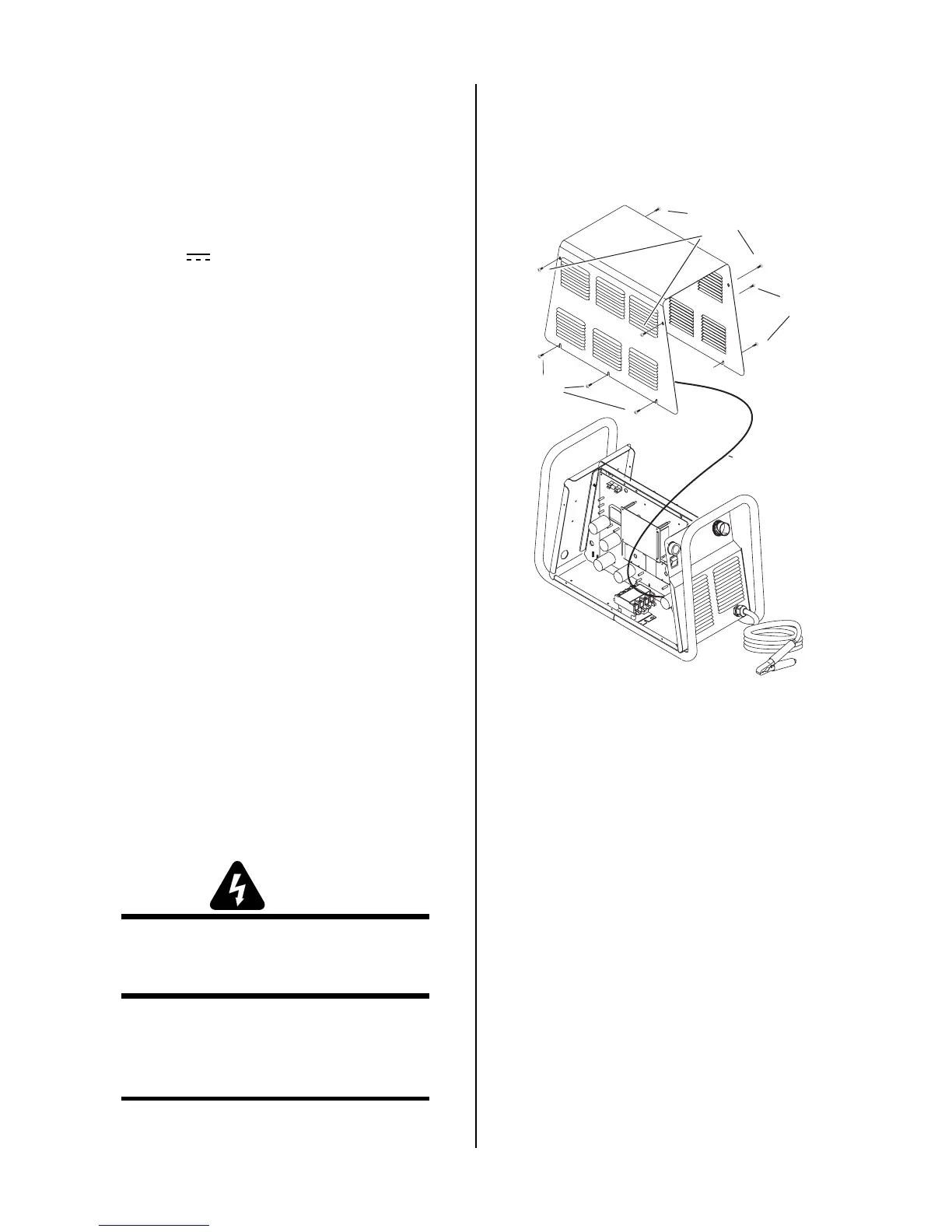
1. Remove the upper screws securing the cover to the
main assembly.
2. Loosen, but do not remove, the lower screws.
NOTE
There is a ground wire attached from the cover to
the main body of the unit.
3. Carefully lift the cover off the unit, and remove the nut
securing the ground wire to the side panel.
4. Re-install the cover by reversing the above steps.
Art # A-03792
Lower
screws
Upper screws
Ground wire
Lower
screws
Cover Removal
Locate your symptom below:
A. Main power line fuses blow as soon as main
disconnect is closed
1. Input power cable installed incorrectly or defective
power cord.
a. Check that the input power cable is not defec-
tive or installed incorrectly. Section 4.10-D il-
lustrates wiring connections.
2. Main input contactor (W1) stuck.
a. Check contactor. Replace if stuck.
B. Main power line fuses blow immediately after the
ON/OFF Switch is turned on.
1. Faulty Input Diode
a. Test Input Diode per Subsection 4.10-C; repair
as necessary.