Manual 0-2957 6-7 PARTS LISTS
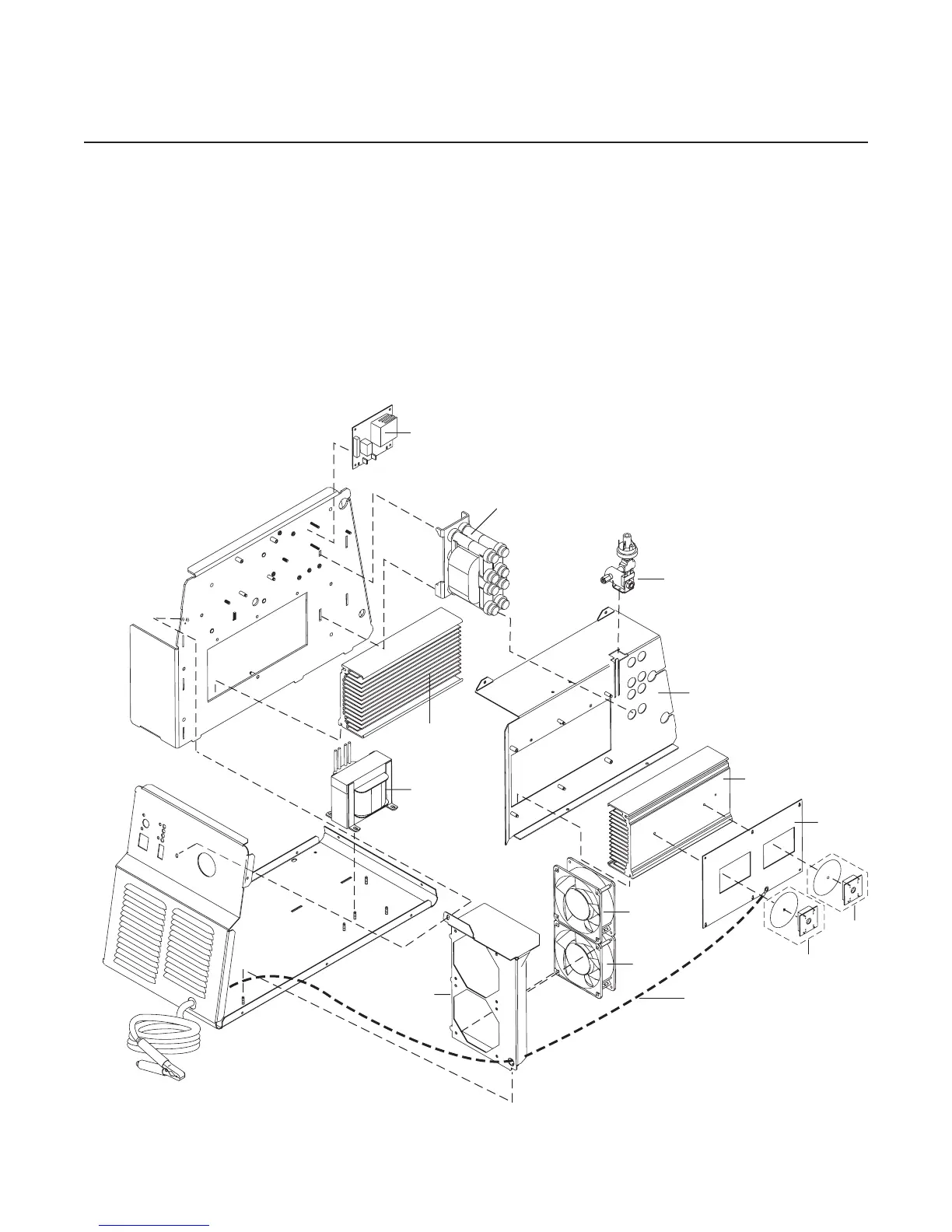
6.07 Right Side Internal Component Replacement Parts
Item # Qty Description Ref #. Catalog #
1 1 Assembly, Pressure Switch/Solenoid Sol1, Ps1 9-8329
2 1 Assembly, Pilot Board 9-8337
3 1 Fan, 220V, 115 CFM 9-7687
4 1 Assembly, Main Transformer T5
for 208/230-Volt units 9-8589
for 400 Volt and 415-Volt units 9-8603
for 460-Volt units 9-8584
for 600-Volt units 9-8635
5 1 Assembly, Output Inductor L1 9-8591
6 1 Assembly, Output Power PCB 9-7988
7 1 Assembly, Output Diode PCB 9-8580
1 Round Thermal Pad
NOTE: Illustration may vary slightly from unit.
2
3
5
1
7
4
6
Art # A-03718
Work Cable
Output Diode
Heatsink
IGBT Heatsink
Heatsink
Shroud
Fan
Shroud
3
7