TROUBLESHOOTING 4-4 Manual 0-2957
4.06 Circuit Fault Isolation
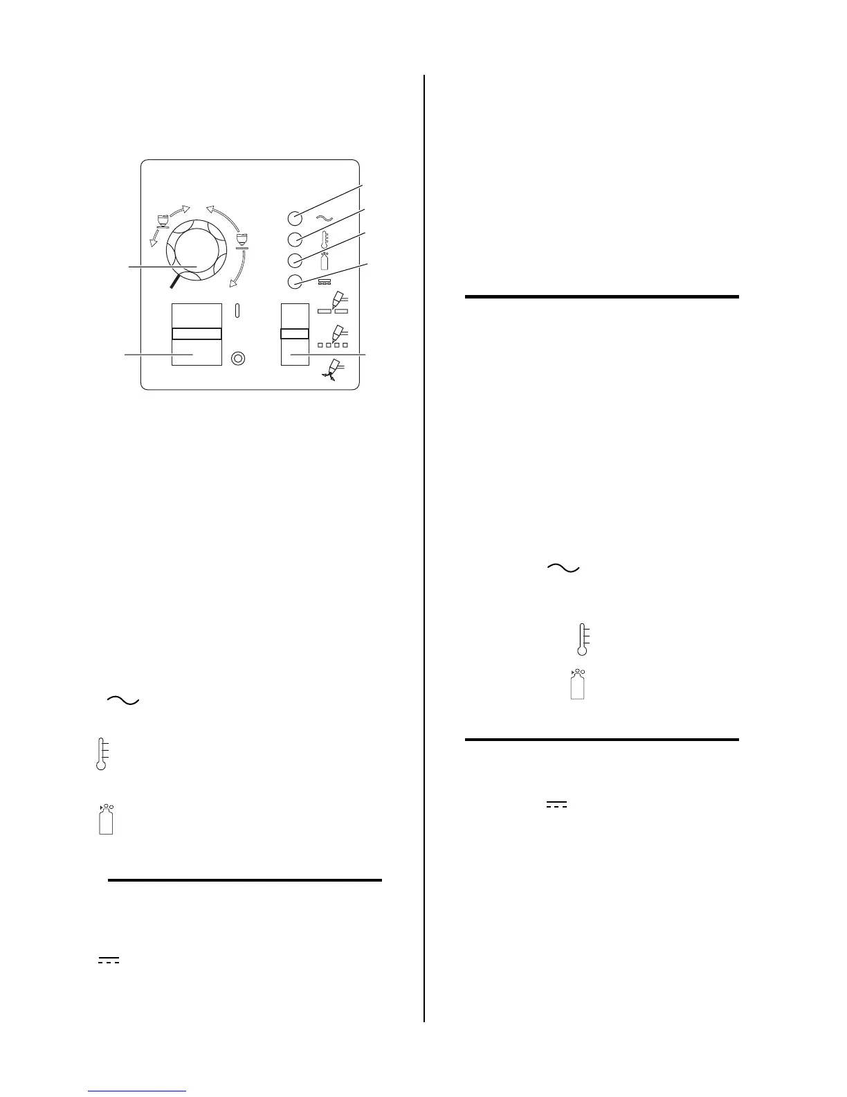
A. Controls and Indicators
Art # A-03845
A
20
40
60
3
5
4
1
2
6
7
1. ON/OFF switch. This switch controls AC power to the
unit. Up is ON, down is OFF.
2. RUN / RAPID AUTO RESTART / SET switch. This
switch controls gas flow to the torch. Up is RUN, for
general torch operation. Center position is RAPID
AUTO RESTART, for an uninterrupted restart when
cutting expanded metal or in gouging or trimming op-
erations. Down is SET, for setting gas pressure and
purging lines.
3. Current control knob (A) This control regulates cur-
rent to the torch. At output settings over 40 amps, cir-
cuitry in the power supply automatically reduces out-
put current to 40 amps if the torch tip contacts the
workpiece.
4. AC indicator When lit, indicates operating
power is present in the unit.
5. TEMP indicator turns on when internal sensors
detect temperatures above normal limits.
6. GAS indicator Indicates adequate gas pressure
for power supply operation.
NOTE
Minimum gas pressure for power supply opera-
tion is lower than the minimum for torch opera-
tion.
7. DC indicator Indicates DC power output circuit
is active. (Torch must be activated).
B. Initial Setup Conditions
This section is to help isolate the defective circuit before
troubleshooting, identify symptoms, and test the unit for
proper operation. Follow the instructions as given to iden-
tify the possible symptom(s) and the defective circuit.
After repairs are complete, run the following tests again
to verify that the unit is fully operational.
1. Connect gas supply to rear of Power Supply.
2. Turn on gas supply and set operating pressure per
pressure setting label on power supply.
NOTE
Minimum gas pressure for power supply operation
is lower than the minimum for torch operation.
3. Set the Power Supply controls as follows:
• ON/OFF switch to OFF (Down)
• RUN / RAPID AUTO RESTART / SET switch to
SET (Down)
• CURRENT control (A) to maximum
C. Main Input and Internal Power Tests
1. Connect main AC power to the unit.
2. Set the Power Supply ON/OFF switch to ON (up) and
note the following:
• AC indicator is steady ON
• Main PCB Relay energizes, pulling in main input
contactor (W1)
• TEMP Indicator is OFF
• GAS Indicator is ON if input pressure is suffi-
cient for power supply operation.
NOTE
Minimum gas pressure for power supply operation
is lower than the minimum for torch operation.
• DC indicator is OFF
• Gas flows
• Fans operate
3. Set the Power Supply RUN / RAPID AUTO RESTART
/ SET switch to the RUN (up) position and note the
following:
• Gas flow stops
This completes the Main Input and Internal Power Tests.
If the above are all correct then proceed to paragraph 'D'. If
not, note the symptom and proceed to Subsection 4.07,
Main Input and Internal Power Problems.