TROUBLESHOOTING 4-14 Manual 0-2957
4.09 Main Arc Problems
Locate your symptom below:
A. Main cutting arc will not start
1. Work cable not connected.
a. Connect work cable.
2. Holding too high of a standoff.
a. Refer to recommended standoff heights. Adjust
as needed.
3. Workpiece is painted or rusty.
a. Clean workpiece.
4. Faulty Main PC Board or Logic Board.
a. Measure for ±0 vdc at TP2 to TP1 on the Logic
Board when attempting to transfer. Refer to
Logic Board Layout.
• If voltage goes to 0 vdc replace Output Board.
• If not, replace Main PC Board.
5. Faulty Main Input Contactor.
a. Check per Subsection 4.10-D.
B. When operating the amperage drops off after the
main cutting arc starts.
1. Torch tip contacts workpiece
Lift the torch tip off the work. At output settings
over 40 amps, circuitry in the power supply au-
tomatically reduces output current to 40 amps if
the torch tip contacts the workpiece.
2. Faulty Pilot Board
a. With power off and wires E58 and E62 discon-
nected from the pilot board, measure for conti-
nuity between terminals #E58 and #E62. If con-
tinuity is found, replace Pilot Board.
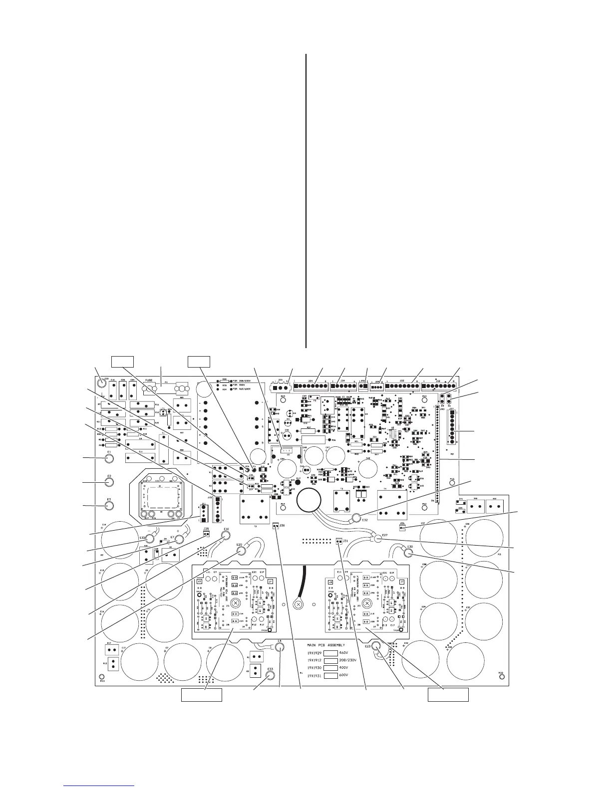
Art # A-03651
INPUT
DIODE
E22
E1
E2
E3
TP1
E7
E15
TP4
U1
J24
J32
J29
E10
E20
E4
J30
E33
J18
J26
E27
J23
E30
J33
J31
E23
E32
J27
J25
IGBT A
IGBT B
J43
J34
J11
J15
J16
J17
E6
E5
FUSE
Main Printed Circuit Board Layout (logic board not shown)