CUTMASTER 58
OPERATION Manual 0-5544
4T-2
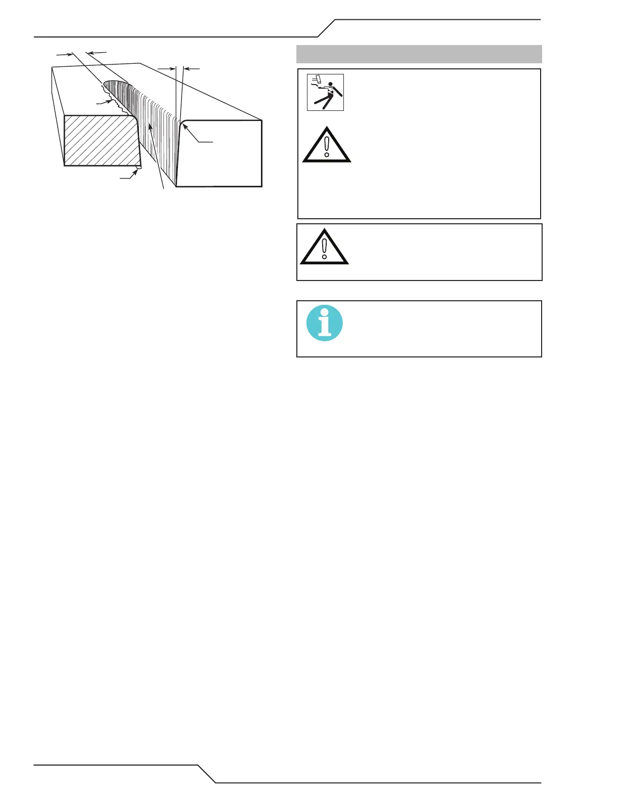
Kerf Width
Cut Surface
Bevel Angle
Top Edge
Rounding
Cut Surface
Drag Lines
Dross
Build-Up
Top
Spatter
A-00007
Cut Quality Characteristics
Cut Surface
The desired or specied condition (smooth or rough)
of the face of the cut.
Nitride Build - Up
Nitride deposits can be left on the surface of the cut
when nitrogen is present in the plasma gas stream.
These buildups may create diculties if the material is
to be welded after the cutting process.
Bevel Angle
The angle between the surface of the cut edge and a
plane perpendicular to the surface of the plate. A per-
fectly perpendicular cut would result in a 0° bevel angle.
Top - Edge Rounding
Rounding on the top edge of a cut due to wearing from
the initial contact of the plasma arc on the workpiece.
Bottom Dross Buildup
Molten material which is not blown out of the cut area
and resolidies on the plate. Excessive dross may re-
quire secondary cleanup operations after cutting.
Kerf Width
The width of the cut (or the width of material removed
during the cut).
Top Spatter (Dross)
Top spatter or dross on the top of the cut caused by
slow travel speed, excess cutting height, or cutting tip
whose orice has become elongated.
4T.03 General Cutting Information
WARNING
Disconnect primary power at the source before dis-
assembling the power supply, torch, or torch leads.
Frequently review the Important Safety Precautions
at the front of this manual. Be sure the operator is
equipped with proper gloves, clothing, eye and ear
protection. Make sure no part of the operator’s body
comes into contact with the workpiece while the
torch is activated.
!
CAUTION
Sparks from the cutting process can cause damage
to coated, painted, and other surfaces such as glass,
plastic and metal.
NOTE!
Handle torch leads with care and protect them from
damage.
Piloting
Piloting is harder on parts life than actual cutting be-
cause the pilot arc is directed from the electrode to the
tip rather than to a workpiece. Whenever possible, avoid
excessive pilot arc time to improve parts life.
Torch Standoff
Improper stando (the distance between the torch tip
and workpiece) can adversely aect tip life as well as
shield cup life. Stando may also signicantly aect the
bevel angle. Reducing stando will generally result in
a more square cut.
Edge Starting
For edge starts, hold the torch perpendicular to the
workpiece with the front of the tip near (not touching)
the edge of the workpiece at the point where the cut is
to start. When starting at the edge of the plate, do not
pause at the edge and force the arc to "reach" for the
edge of the metal. Establish the cutting arc as quickly
as possible.
Direction of Cut
In the torches, the plasma gas stream swirls as it leaves
the torch to maintain a smooth column of gas. This swirl
eect results in one side of a cut being more square than
the other. Viewed along the direction of travel, the right
side of the cut is more square than the left.