Manual 0-2844 2-1 INTRODUCTION
SECTION 2:
INTRODUCTION
2.01 Scope of Manual
This manual contains descriptions, operating instructions
and basic maintenance procedures for the CE CutMaster
Plasma Cutting Power Supply only. Servicing of this
equipment is restricted to properly trained personnel; un-
qualified personnel are strictly cautioned against attempt-
ing repairs or adjustments not covered in this manual, at
the risk of voiding the Warranty.
Read this manual thoroughly. A complete understand-
ing of the characteristics and capabilities of this equip-
ment will assure the dependable operation for which it
was designed.
NOTE
Refer to the Torch Manual provided with this Power
Supply for torch and cutting information.
2.02 General Description
The power supply includes all control circuitry, electri-
cal and gas inputs and outputs, pilot circuitry, primary
input power cable, and work cable & clamp.
NOTE
Refer to Section 2.04 for a list of power supply op-
tions and accessories.
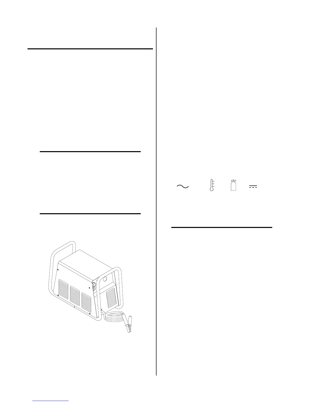
A-02766
CE CutMaster Power Supply
2.03 Specifications/Design
Features
A. Power Supply Technical Specifications
The following specifications apply to the Power Supply
only:
1. Front Panel Features
• Main power ON/OFF switch
• RUN/SET switch
• output current control
• torch leads access
• work lead
2. Rear Panel Features
• Primary input power cable
• Gas pressure regulator/filter assembly
• Gas supply connection
• Grounding stud (CE CutMaster 75 & 100)
3. Front Panel Indicators
AC
, TEMP , GAS , DC
4. Input Power (See Note)
400VAC (±10%), Three Phase. Power Supply includes
4-conductor input power cable with filtering beads.
NOTE
Refer to Appendix 1 for input wiring requirements.
5. Output Power
Continuously variable.
• CE CutMaster 50: from 20 to 40 amps maximum.
• CE CutMaster 75: from 15 to 60 amps maximum.
• CE CutMaster 100: from 20 to 80 amps maximum.