Manual 0-2844 4-1 OPERATION
SECTION 4:
OPERATION
4.01 Introduction
This section describes the power supply operating con-
trols and procedures, identifies the front and rear com-
ponents, and describes the operating procedures.
4.02 Product Features
This subsection provides specific functional descriptions
of the power supply features, controls, and indicators.
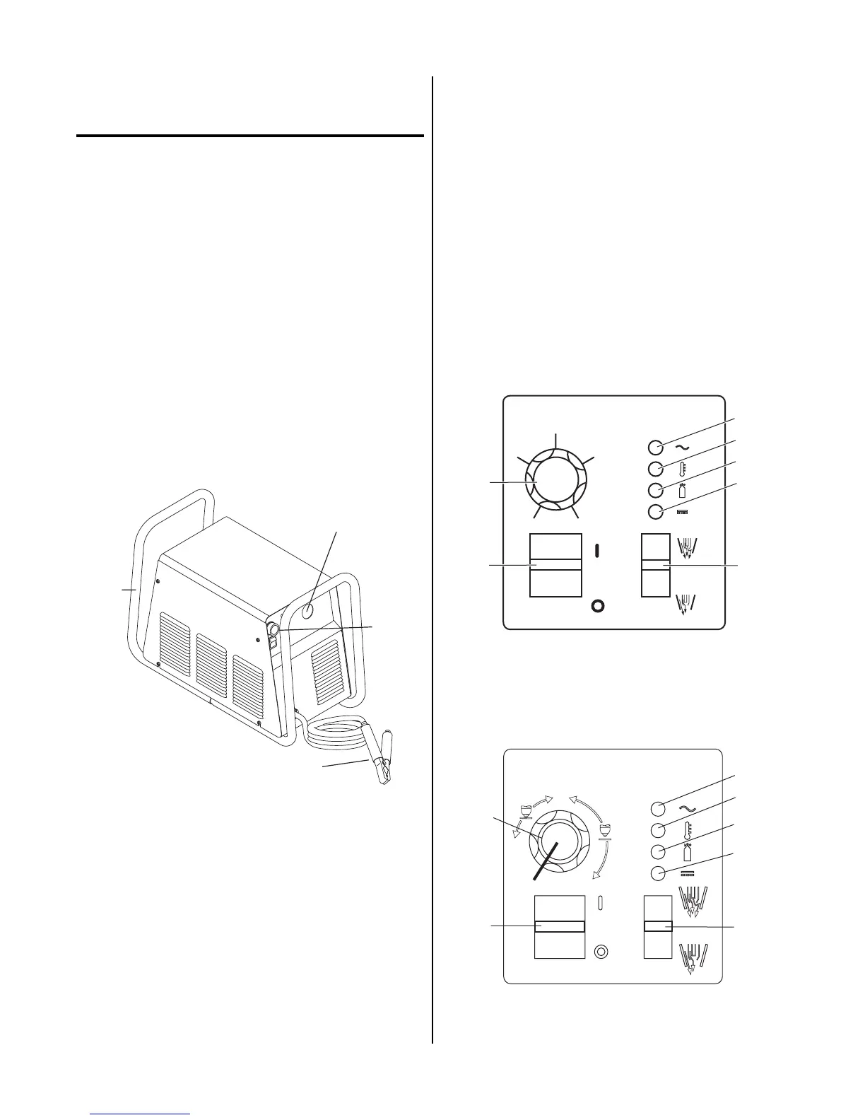
A. Front and Side Panel Features
1. Control Panel
All operator controls, except gas pressure adjustment,
are located on this panel: power ON/OFF switch,
RUN/SET switch; CURRENT control; indicators for
AC Power, TEMP, GAS, and DC.
A-02772
1
2
3
4
Front and Side Panel Features
2. Torch Leads Input
Hole in the front panel to feed the torch leads through
to the internal bulkhead connections.
3. Work Cable and Clamp
20 ft. (6.1 m) work cable with clamp, factory installed.
4. Roll Handle/Torch Leads Wrap
The torch leads and work cable wrap around the
handle for easy storage.
5. Torch Bulkhead Panel
The torch bulkhead panel is under the power supply
cover.
• Pilot Lead Stud
Connects the pilot control wire on the torch to the unit.
• Control Cable Connector
Connects the torch switch to the unit. In machine torch
applications connects the torch switch on the pendant
to the unit.
• Gas/Power Lead Connection
Connects the torch gas/negative lead to the unit.
B. Control Panel Features
A-03641
1
20
25
30
35
40
4
5
6
7
2
3
A
Operating Controls (CE CutMaster 50)
1
3
4
5
6
7
2
Operating Controls (CE CutMaster 75, 100)