Manual 0-2844 3-7 INSTALLATION PROCEDURES
C. Remote Pendant Control (Optional)
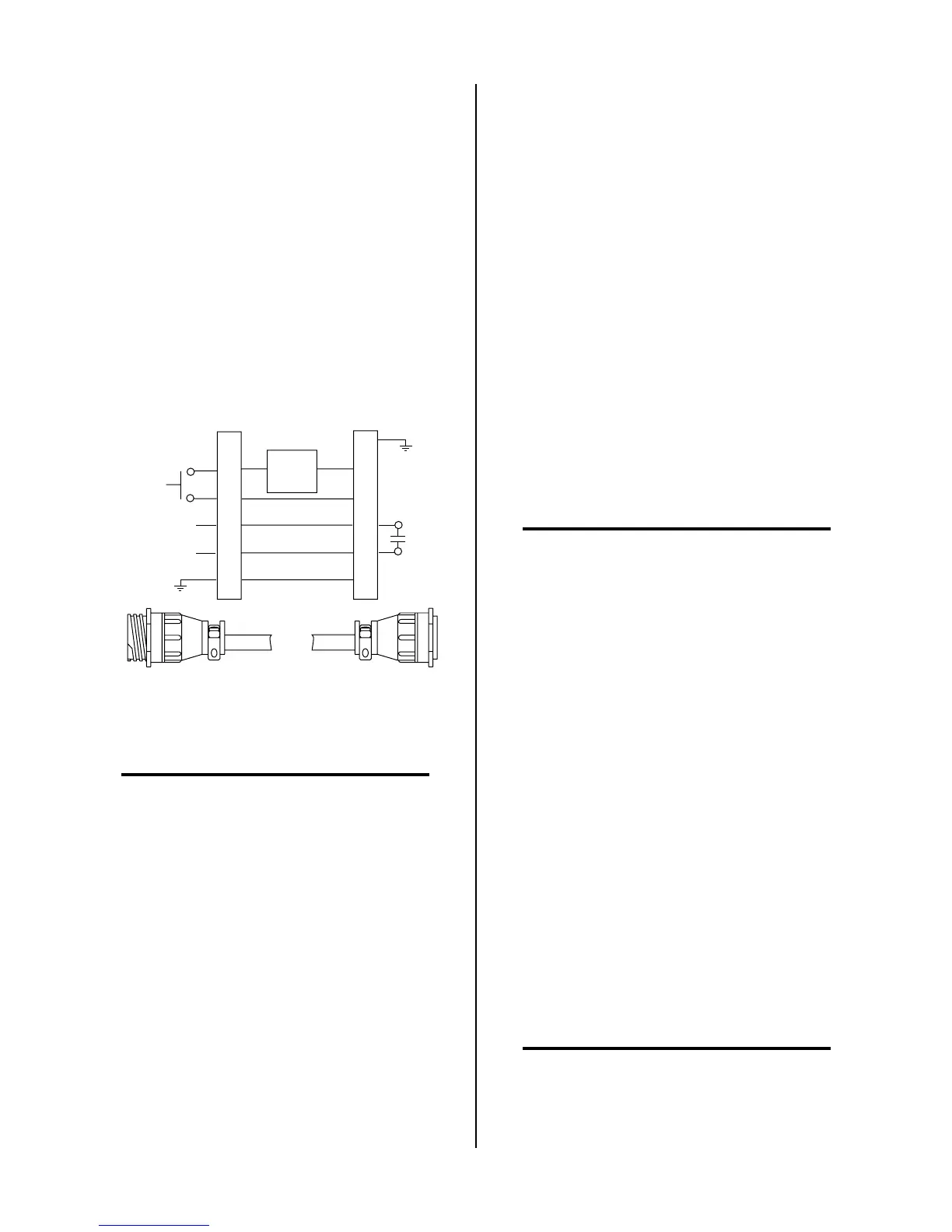
In machine type operations the Power Supply has an
Adapter that has a cable connector supplied at each
end of the Adapter. One end is connected at the fac-
tory to the mating connector on the Power Supply
Bulkhead area. The other end allows connection of a
Remote Pendant. The remote pendant lead connector
allows connection to a remote pendant or CNC cable
while using Control (PIP) Circuit connections in the
Torch Assembly.
Connect the remote pendant control cable to the con-
nector provided on the Adapter from the Power Sup-
ply.
2
3
4
12
14
13
Torch Control
Cable Connector
Remote Pendant/CNC
Cable Connector
PIP
Circuit
Control
OK-To-Move
3
4
12
14
13
A-01366
Remote Pendant Connector Diagram
NOTE
Refer to Appendix 3, Torch Control Cable Wiring
Diagram For Mechanized Systems, for detailed
schematic of the Adapter.
3.08 Ground Connections For
Mechanized Applications
A. Electromagnetic Interference (EMI)
Pilot arc initiation generates a certain amount of electro-
magnetic interference (EMI), commonly called RF noise.
This RF noise may interfere with other electronic equip-
ment such as CNC controllers, remote controls, height con-
trollers, etc. To minimize RF interference, follow these
grounding procedures when installing mechanized sys-
tems:
B. Grounding
1. The preferred grounding arrangement is a single point
or “Star” ground. The single point, usually on the
cutting table, is connected with 1/0 AWG (European
50 mm
2
) or larger wire to a good earth ground (refer to
paragraph ‘C’, Creating An Earth Ground). The
ground rod must be placed as close as possible to the
cutting table, ideally less than 10 ft (3.0 m), but no more
than 20 ft (6.1 m).
NOTE
All ground wires should be as short as possible.
Long wires will have increased resistance to RF fre-
quencies. Smaller diameter wire has increased re-
sistance to RF frequencies, so using a larger diam-
eter wire is better.
2. Grounding for components mounted on the cutting
table (CNC controllers, height controllers, plasma re-
mote controls, etc.) should follow the manufacturer’s
recommendations for wire size, type, and connection
point locations.
For Thermal Dynamics components it is recommended
to use a minimum of 10 AWG (European 6 mm
2
) wire
or flat copper braid with cross section equal to or greater
than 10 AWG connected to the cutting table frame. The
connection point must be clean bare metal; rust and
paint make poor connections. For all components,
wires larger than the recommended minimum can be
used and may improve noise protection.
3. The cutting machine frame is then connected to the
“Star” point using 1/0 AWG (European 50 mm
2
) or
larger wire.
4. The plasma power supply work cable (see NOTE) is
connected to the cutting table at the single point “Star”
ground.
NOTE
Do Not connect the work cable directly to the ground
rod.