Manual 0-2844 3-3 INSTALLATION PROCEDURES
C. Connecting Gas Supply to Unit
The gas supply is connected to the Regulator/Filter As-
sembly located on the rear of the unit. The connection is
the same for compressed air or high pressure gas cylin-
ders.
Connect the gas supply as follows:
1. If an optional air line filter is to be installed, refer to
procedures in subsection 3.06-D.
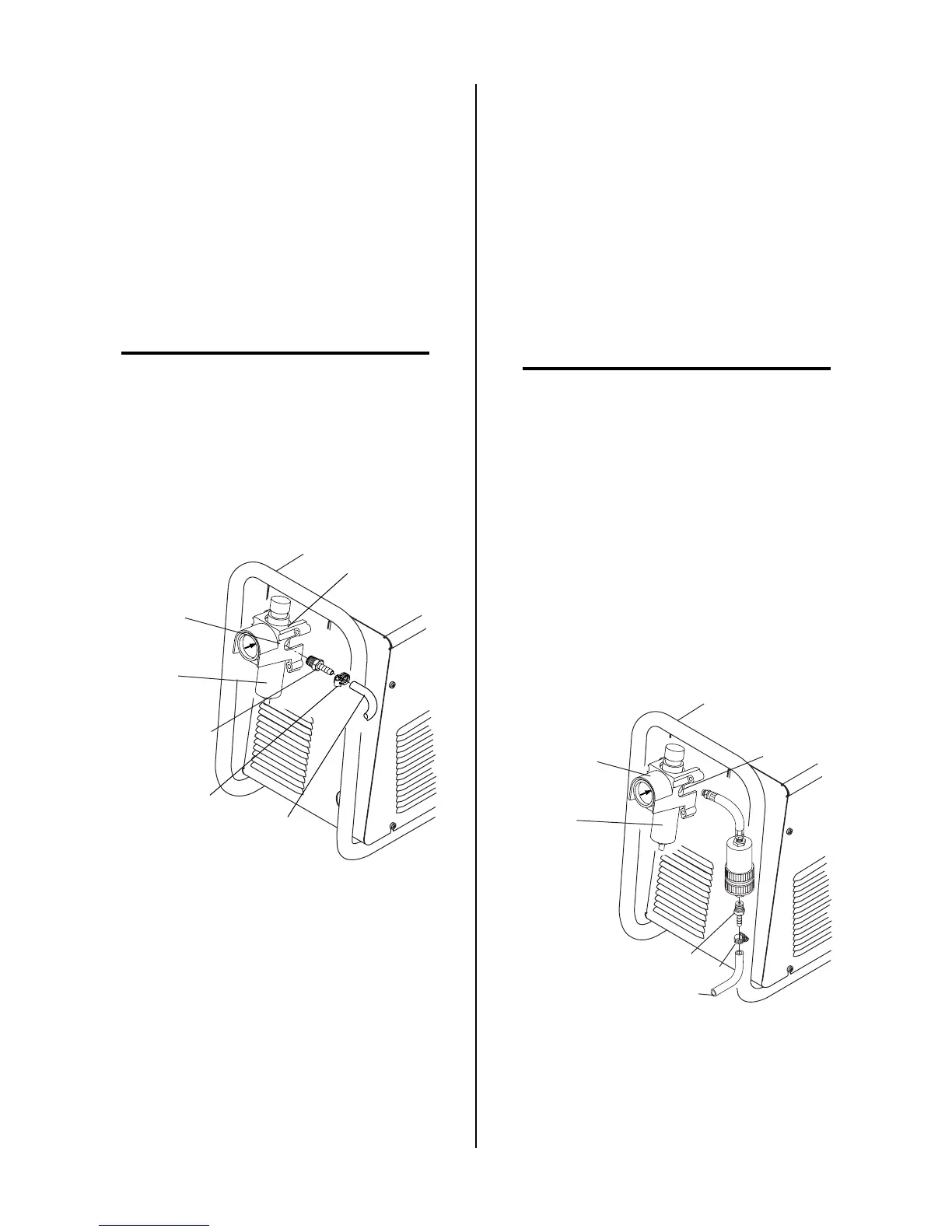
2. Connect the gas line to the filter. A typical installa-
tion using a barbed fitting is illustrated; other fittings
may be used.
NOTE
For a secure seal, apply thread sealant to the fitting
threads, according to manufacturer's instructions.
Do Not use Teflon tape as a thread sealer, as small
particles of the tape may break off and block the
small gas passages in the torch.
3. Connect the gas line to the Regulator/Filter Assem-
bly.
Art # A-02999
Hose Clamp
1/4 NPT to 1/4"
(6mm) Fitting
Regulator/Filter
Assembly
Inlet Port
Gas Supply
Hose
Bowl
Gas Connection to Regulator/Filter Assembly
D. Installing Optional Air Filter Kits
Additional filtering is recommended when using air from
a compressor to insure that moisture and debris from the
supply hose does not enter the torch. Although the Regu-
lator/Filter Assembly does have its own filter, the op-
tional Single-Stage Air Filter Kit or optional Two-Stage
Air Filter Kit are recommended for improved filtering.
1. Optional Single-Stage Air Filter Kit
This optional in-line air filter for use on compressed
air shop systems is highly effective at removing mois-
ture and particulate matter from the air stream to at
least 0.85 microns.
NOTE
For a secure seal, apply thread sealant to the fitting
threads, according to manufacturer's instructions.
Do Not use Teflon tape as a thread sealer as small
particles of the tape may break off and block the
small gas passages in the torch. Connect the gas
supply as follows:
a. Attach the Single-Stage Filter Hose to the Regu-
lator/Filter Assembly inlet port as shown be-
low.
b. Connect the gas line to the optional filter. A
typical installation using a barbed fitting is il-
lustrated; other fittings may be used.
c. Attach the gas supply hose to the Single-Stage
Filter Assembly.
Art # A-03000
Regulator/Filter
Assembly
Inlet Port
Bowl
1/4 NPT Hose Fitting
1/4" (6 mm) Gas Supply Hose
Hose Clamp
Optional Single Stage Filter Installation