January 8, 2009 2 Manual 0-2880 Rev AB
C. Current Rating (Refer to Note)
SL60 & SL100 Current Ratings
SL60 Torch & Leads
SL100 Torch & Leads
Up to 60 Amps, DC,
Straight Polarity
Up to 100 Amps, DC,
Straight Polarity
NOTE
Power Supply characteristics will determine mate-
rial thickness range.
D. Torch Ratings
Ambient
Tem
erature
104° F
40° C
Duty Cycle
100% @ 60 Amps @ 400 scfh
Maximum Current
60 Amps
Voltage (V
peak
)
500V
Arc Striking Voltage
7kV
SL60 Torch Ratin
s
Ambient
Tem
erature
104° F
40° C
Duty Cycle
100% @ 100 Amps @ 400 scfh
Maximum Current
100 Amps
Voltage (V
peak
)
500V
Arc Striking Voltage
7kV
SL100 Torch Ratin
s
E. Type of Cooling
Combination of ambient air and gas stream through
torch.
F. Gas Requirements
Gas (Plasma and Secondary) Compressed Air
Operating Pressure
Refer to NOTE
60 - 75 psi
4.1 - 5.2 bar
Maximum Input Pressure 125 psi / 8.6 bar
Gas Flow (Cutting and Gouging)
300 - 500 scfh
(142 - 235 lpm)
SL60 and SL100 Torch Gas Specifications
WARNING
This torch is not to be used with oxygen (O
2
).
NOTE
Operating pressure varies with torch model, oper-
ating amperage, and torch leads length. Refer to
gas pressure settings chart for each model.
G. Direct Contact Hazard
For exposed tip the recommended standoff is 1/8" - 1/4"
(3 - 6.4 mm).
H. Parts-In-Place (PIP) Circuit - 12 vdc
The torch and leads include circuitry called Parts-In-
Place (PIP). This circuit includes a switch located at
the torch head. The shield cup closes this switch when
properly installed. The torch will not operate if this
switch is open.
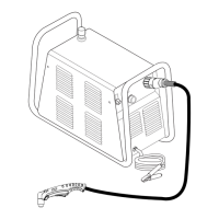
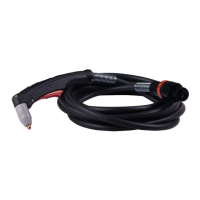
Connecting Torch
There are two types of connection for the Torch Leads. One
type uses the Thermal Dynamics ATC connector. The other
uses O2B connections for gas and circuitry. Both types require
an adapter kit sold separately.
ATC Connectors
Follow the instructions provided with the adapter kit to con-
nect the adapter to the power supply.
Inspect the halves of the ATC Connector. Align the male con-
nector with the female receptacle and push them together by
hand until they seat fully. Turn the Locking Ring until it pulls
the halves of the connector together fully. Do not use tools to
tighten the connector. If there is any resistance to the ring
turning, pull the halves of the connector apart, realign the inner
components, ensure that the threaded components are aligned,
and push the halves of the connector together again.
O2B Connectors
Leads with O2B connectors are connected to the power supply
using adapter kits sold separately. Follow the instructions
provided with the adapter kit to connect the gas and electrical
lines to the power supply.