January 8, 2009 3 Manual 0-2880 Rev AB
Spare Parts Label
The parts kit provided with the torch includes an adhe-
sive label. Select the small perforated section showing the
appropriate pressure setting for the amperage output and
leads length to be used with this torch. Refer to the charts.
Apply this section in the 'Gas Supply' area of the label
under the 'Recommended Operating Pressure' text. Dis-
card any pressure setting sections of the label that will not
be used. Apply the large label to the power supply, where
the operator can see it for easy reference.
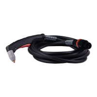
Torch Parts Selection
Refer to the Consumables Selection Chart for the various torch
parts for the application and operation.
WARNINGS
Disconnect primary power to the system before dis-
assembling the torch or torch leads.
DO NOT touch any internal torch parts while the
AC indicator light of the Power Supply is ON.
The shield cup (or shield cup body and shield cap or deflector)
holds the tip and starter cartridge in place. Position the torch
with the shield cup facing upward to keep these parts from
falling out when the cup is removed.
Change the torch parts as follows:
1. Unscrew and remove the shield cup from the torch
head.
Art # A-03417
Electrode
Start Cartridge
Tip
Shield Cup
Assembly
Torch Head
2. Tilt the torch head to remove the tip and starter car-
tridge.
3. Fit the desired starter cartridge and tip onto the electrode.
NOTE
Refer to the consumables selection chart for the proper
combination of torch parts, including shield cups
and caps.
4. Hand tighten the shield cup until it is seated on the torch
head. Do not use tools to tighten the cup. If resistance is
felt when installing the cup, check the threads before pro-
ceeding.
NOTE
When operating the torch in a normal condition,
a small amount of gas vents through the gap be-
tween the shield cup and the torch handle. Do not
attempt to overtighten the shield cup as irrepa-
rable damage to internal components may result.
Gouging Parts Selection
Select gouging tips according to the desired gouge profile.
Gouging parameters shown are based on a 35° approach angle.
Output Range Depth Width
Tip A 40 Amps Max. Shallow Narrow
Tip B 40-100 Amps Deep Narrow
Tip C 40-100 Amps Moderate Moderate
Tip D 40-100 Amps Shallow Wide
Gouging Profiles
Operating Gas Pressure
Set gas pressure at the power supply regulator according to the
following charts. These charts are a guide only; adjust as nec-
essary for best performance.
Tip
20' / 6.1 m 50' / 15.2 m
30A, 40A,
50/55A, 60A
65 psi / 4.5 bar 75 psi / 5.2 bar
Leads Length
SL60 Gas Pressure Settings
Tip
Up to 25' / 7.6 m 50' / 15.2 m
30A, 40A,
50/55A, 60A,
70A, 80A
60 psi / 4.1 bar 65 psi / 4.5 bar
90/100A 65 psi / 4.5 bar 70 psi / 5.2 bar
SL100 Gas Pressure Settings
Leads Length