Unit Description (Rev. 04/03)
8
UNIT PROTECTION DEVICES
1. FUSES. A number of fuses are located on the relay
board. The sizes and functions are shown in Table 1.
2. HIGH PRESSURE CUTOUT. The high pressure cut-
out is a pressure sensitive switch that is located in the
compressor discharge manifold. If the discharge pres-
sure rises above 450 psig (3103 kPa) for R-404A sys-
tems or 325 psig (2088 kPa) for R-134a systems, the
switch opens the 8D circuit to the fuel solenoid, which
stops the engine.
3. HIGH PRESSURE RELIEF VALVE. The high pres-
sure relief valve is designed to relieve excess pressure
within the refrigeration system. The valve is a spring-
loaded piston that lifts off its seat when refrigerant
pressure exceeds 500 psig (3447 kPa). The valve will
reseat when the pressure drops to 400 psig (2758 kPa).
The valve could possibly leak refrigerant after it has
relieved excess pressure. Tapping the valve lightly may
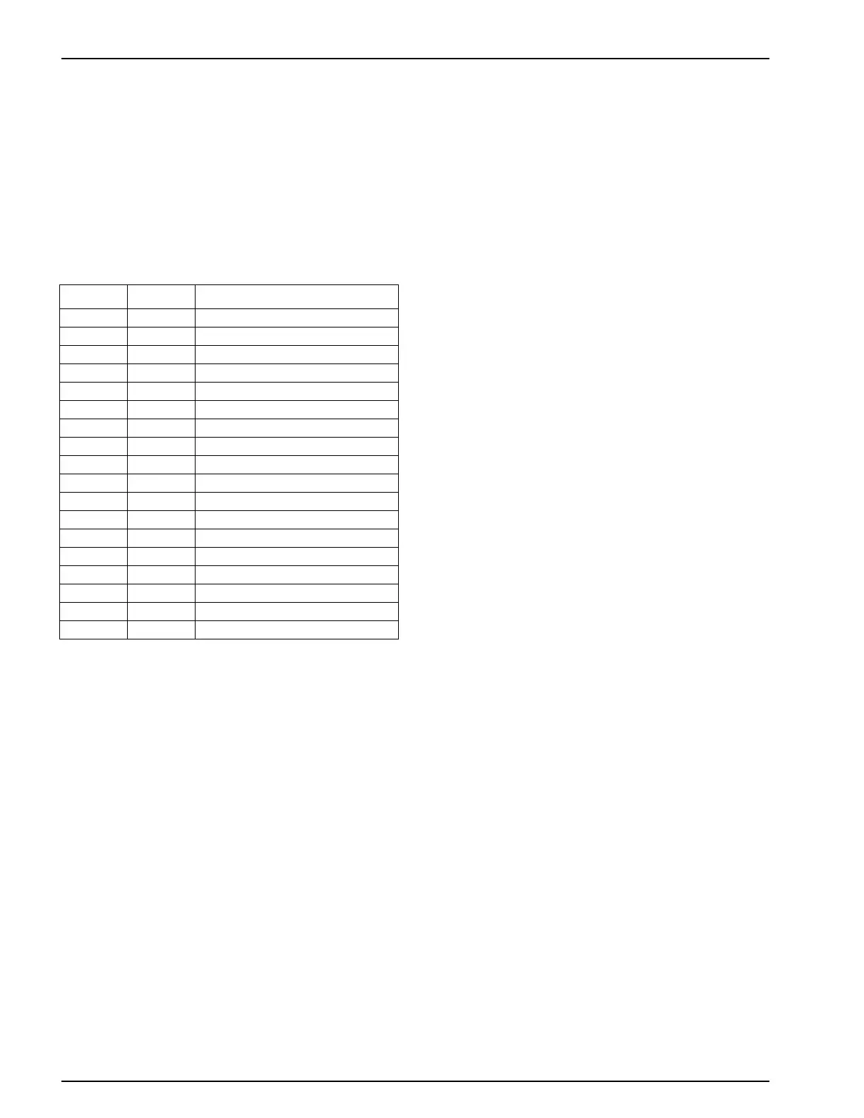
Table 1: Relay Board Fuse Size and Function
Fuse Size Function
F200 3A 2P Power to Microprocessor
F202 3A Oil Level Switch
F300 3A Pilot Solenoid
F301 3A TherMax Solenoid
F302 3A Alternator Relay
F303 3A Damper Relay
F304 3A Starter Relay
F305 3A On/Run Relay
F306 3A Preheat Relay
F037 3A Not Used
F308 3A Not Used
F309 15A Alternator Excitation
F310 15A Damper Solenoid
F311 3A Motor Reset Solenoid
F400 3A Motor Starter
F401 10A Fuel Solenoid and Fuel Pump
F402 10A Throttle Solenoid
F403 3A Heater Contactor
help the valve reseat and SEAL PROPERLY. The valve
is non-repairable and requires no adjustment. If the
valve fails to reseat properly, remove the refrigerant
charge and unscrew and replace the valve.
The high pressure relief valve is located on a high pres-
sure line near the condenser. Its location is such that
when the pressure is expelled from the valve, it would
be directed away from anyone servicing the unit.
4. LOW OIL LEVEL SWITCH. The low oil level switch
closes if the oil drops below a certain level. If it stays
closed for a specified time, the microprocessor will
shut the unit down and record alarm code 66.
5. PREHEAT BUZZER. The preheat buzzer sounds when
the CYCLE-SENTRY system energizes the glow plugs.
UNIT OPERATION
Pre-trip Inspection (Before Starting Unit)
The following pre-trip inspection should be completed
before starting the unit and loading the trailer. While pre-
trip inspection is not a substitute for regularly scheduled
maintenance inspections, it is an important part of the pre-
ventive maintenance program designed to head off operat-
ing problems and breakdowns before they happen.
1. FUEL. The diesel fuel supply must be adequate to
guarantee engine operation to the next check point.
2. ENGINE OIL. The engine oil level should be at the
FULL mark with the dipstick NOT routed (threaded)
into the oil pan. Never overfill.
3. COOLANT. The engine coolant must have antifreeze
protection to -30 F (-34 C). Check and add coolant in
the expansion tank.
CAUTION: Do not remove expansion tank cap while
coolant is hot.
4. BATTERY. The terminals must be clean and tight.