Electrical Maintenance (Rev. 04/03)
38
Air Switch
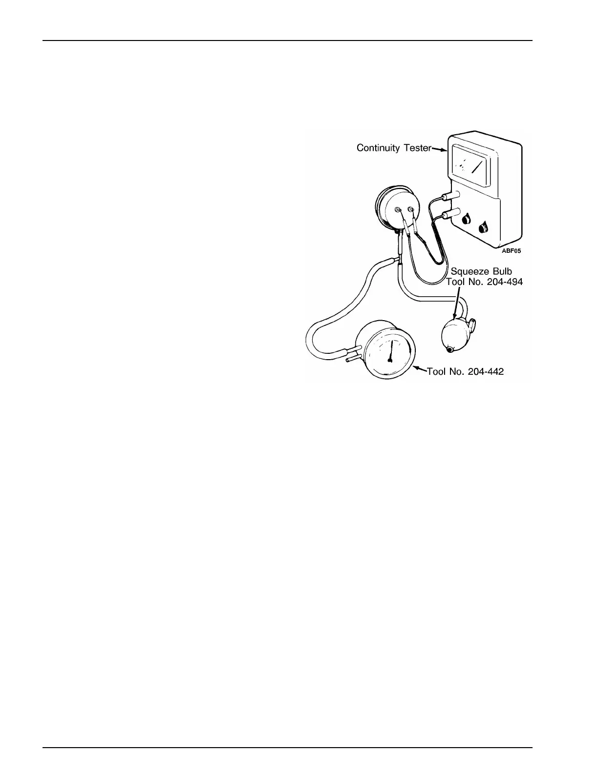
5. If the switch is out of calibration, pressurize the hose
again until the tester indicates 0.9 in. (22.7 mm) H
2
O.
Adjust the screw clockwise or counterclockwise until
the switch closes and the continuity tester indicates a
completed circuit with the gauge reading 0.9 in. (22.7
mm) H
2
O. Release the pressure.
6. Repeat test procedure several times to be sure the set-
ting is correct.
7. Remove the test equipment. Install wire on switch ter-
minal and air sensing tubes on air switch. The BLACK
hose from the high pressure or air inlet side of the evap-
orator coil goes on the hose fitting on the side of the air
switch stamped BLACK. The CLEAR hose from the
low pressure or air outlet side of the evaporator coil
goes on the hose fitting on the side of the air switch
stamped CLEAR.
NOTE: Route hoses for continuous slope to avoid conden-
sate traps.
If too much frost continues to accumulate before defrost,
decrease the pressure setting. Turn the adjustment screw
counterclockwise.
If defrost action occurs with too little frost accumulation,
increase the pressure setting. Turn the adjustment screw
clockwise.
Testing Air Switch
HIGH CAPACITY THERMAX
™
HEATING
SYSTEM
The High Capacity TherMax
™
Heating System
The high capacity heating system increases the capacity of
the heat mode by making more refrigerant available for use
in the heat mode. This is accomplished by adding an addi-
tional solenoid (TherMax™ solenoid) to the refrigeration
system which opens during the beginning of the heat mode
to move the liquid refrigerant from the condenser to the
accumulator where it can be used in the heat mode. The
sequence of operation for the improved heating system is
from the cool mode to the heat with refrigerant transfer
mode to the heat mode. The heat mode to cool mode opera-
tion is the same as in the past. The bypass check valve, and
the condenser check valve have been eliminated from the
TherMax™ heating system.