C-72 Micro-Tech 9101/9201 Reference Manual, Rev J Thermo Fisher Scientific
After power on, the Micro-Tech starts to update the read buffer with the
register of the read block 0 (scale 1).
The write operation simply consists in sending to the Micro-Tech the
values to write in the registers together with indications to identify what
registers have to be written.
The write telegram is composed of two parts, Header and Data.
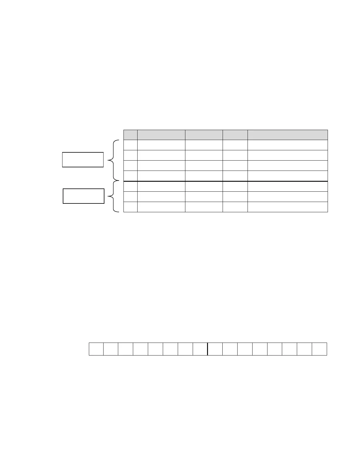
Table C–6. Write Package
ID Register Data Type Offset Description
1 Block Identifier Integer 1 See #1
2 1
Register Integer 2 See #2
3 N° of Registers Integer 3 See #3
4 Stamp Integer 4 See #4
5 Data #1 May vary 5 Value of the first register
…. ……….. ….
n Data #n May vary …. Value of the last register
#1 –BLOCK IDENTIFIER
This register identifies which block of data the master wants to write.
The Micro-Tech can also handle two or more independent scales so it
keeps in memory more copies for each group. The block identifier
register is also used to determine which scale the data refers to.
The first byte (MSB) is used to identify the scale number.
The second byte (LSB) identifies the block number according to
the description of Data Organization Table.
15 8 7 0
SN SN SN SN SN SN SN SN GN GN GN GN GN GN GN GN
SN = Scale number: 00 Scale 1 GN = Block Number e.g See Table C–4
01 Scale 2
02 Scale 3
03 Scale 4
Example:
258 (hex0102) = Scale 2, Block 2 Read “Set and Thresholds” of Scale 2