BA EN 12.2019 Modification 02 from 01.12.19. Copies are not subject to the change service. 34 of 41
Carry out the following work steps:
1. After the PHE has been emptied and the protective covers have been removed, the pipes at the frame
cover (if present) should be disassembled in a manner that ensures that there is enough space for the
cover to be pushed up to the support.
2. In order to facilitate effortless opening, the support rods and the thread of the tensioning screws should
be cleaned.
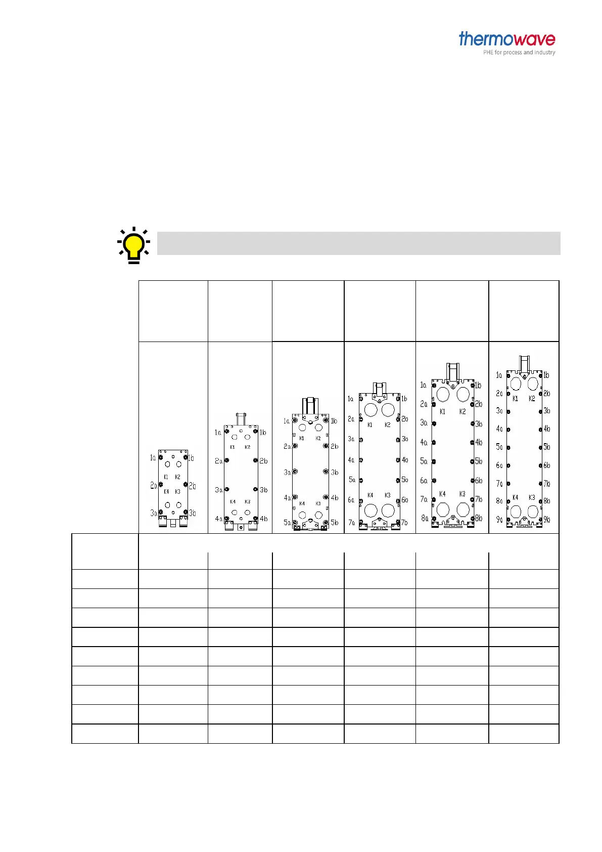
3. The nuts of the tensioning screws are disengaged in accordance with the sequence depicted in figure 32.
In order to facilitate parallel tension release of the plate packet, the nuts should be opened by a
maximum of 2 rotations per pass. The procedure should be repeated in the specified sequence until it
becomes possible to remove the tensioning screws from the clamping slots on the frame plates.
Note down the current tensioning dimension of the plate packet before the PHE is opened, so that
you will able to tension it correctly at the time of reactivation.


 To Next Page