10
2 CONTROLS
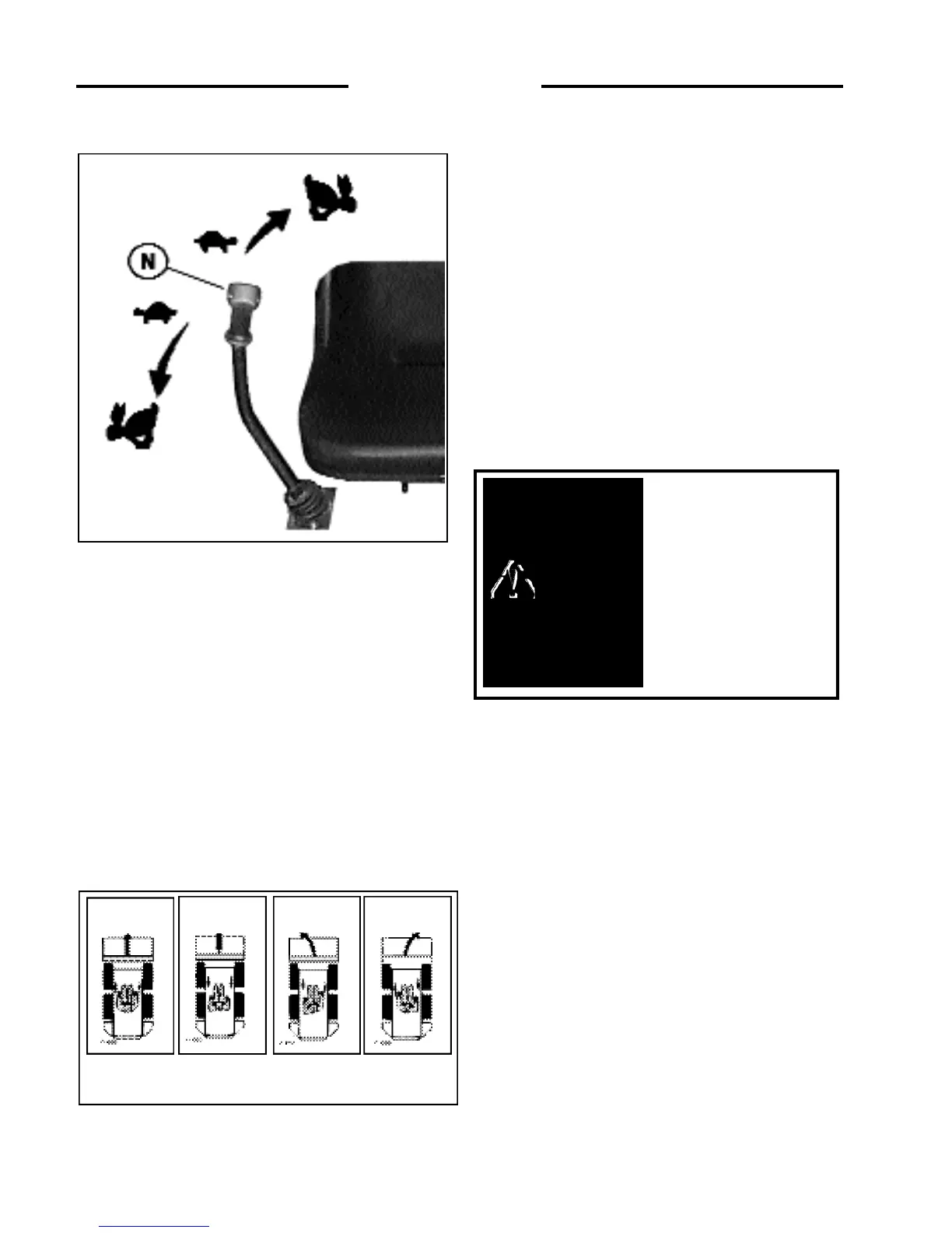
To drive the loader in reverse in a straight line, move both
control levers back the same amount.
The loader is turned by moving one lever further forward
than the other. To turn right move the left lever further than
the right lever, to turn left move the right lever further than
the left lever.
For the loader to turn or “skid-steer” within its own length,
one lever is moved forward and the other back. This causes
the wheels on one side to turn forward and the wheels on
the other side to reverse, turning the loader.
2. 7 HAND CONTROLS
Hand controls to operate the loaders boom and bucket
hydraulic system as well as control the loader travel speed
and direction are available as a factory installed option.
BUCKET CONTROL
The right hand lever controls the bucket tilt cylinders. (Fig. 2.
7A) Moving the control lever to the right will cause the bucket
cylinders to extend, dumping the bucket. Moving the control
lever to the left will cause the bucket cylinders to retract,
rolling the bucket back.
BOOM CONTROL
The left hand lever controls the boom lift cylinders. (Fig. 2.
7A) Moving the control lever to the left will cause the boom
cylinders to extend, raising the loaders boom arms. Moving the
control lever to the right causes the boom cylinders to retract,
lowering the boom. Moving the control lever to extreme right
will place the boom in float position. This allows the bucket to
follow the contour of the ground as the loader moves
backward.
When the control levers are released, they will automatically
return to the neutral position stopping all hydraulic movement
and travel speed. Before exiting the loader, shut off the engine
and ground the attachment by lowering the boom completely
down to the frame. Raise the seat bar to the locked position.
Move both control levers forward and backward to ensure the
steering controls are locked and move both levers to the left
and right to ensure the hydraulic controls are locked before you
get out of the loader.
AUXILIARY HYDRAULICS:
The foot pedal is used to engage the loaders auxiliary hydraulic
circuit to power an attachment such as a post hole auger. (Fig.2.
8A) Pressing on the toe of the pedal provides hydraulic flow to
the female quick-connect coupling located at the front of the
boom arms. Firm pressure on the toe of the pedal will lock it
into detent position providing a continuous flow of hydraulic
oil to the attachment. Pressing on the heel of the pedal provides
hydraulic flow to the quick-connect coupling reversing the
flow of hydraulic oil. If not locked in detent position, releasing
the pedal will cause it to return to the neutral position stopping
all hydraulic flow. Once the pedal is locked in detent, it can be
returned to neutral by tapping the heel of the pedal.
C 3250
Fig. 2. 6A
To avoid personal injury,
lower the boom arms, shut
off the engine, raise the
seat bar and cycle the
hydraulics to ensure they
are locked. Then, unlatch
the seat belt and exit the
loader. Do not enter or exit
with the engine running
unless as specified in this
manual or under specific
service and backhoe
operating procedures.
WARNING
C-696-9
Fig. 2.6B
FORWARD REVERSE
LEFT TURN RIGHT TURN