12
When the auxiliary circuit is not in use, and before starting the
loader, ensure the push-pull switch located on the R.H. side of
the instrument panel is in the off position, otherwise starting
the loader may be difficult or impossible and damage to the
starter may occur.
This machine is equipped with electric solenoid controlled
auxiliary hydraulics, if for any reason the loader stops or looses
current when the electric solenoid is engaged, it can be
disengaged by simply turning off the switch located in the
upper panel, or by depressing the poppet located at either end
of the control valve. (See Fig. 2. 8C).
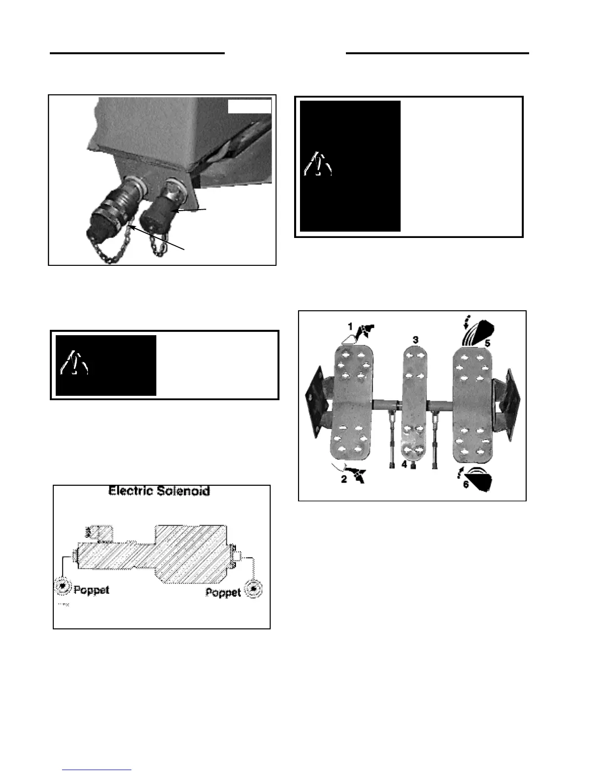
2. 9 FOOT PEDALS
Operation of the boom lift cylinders, bucket tilt cylinders
and auxiliary hydraulic circuit are controlled by foot pedals
(Fig. 2. 9) connected to a hydraulic control valve. The
hydraulic control valve is a series type valve which allows
simultaneous use of both the boom lift and bucket tilt
circuits. The control valve is equipped with a relief valve for
circuit protection.
Boom Lift –
The L.H. pedal is the boom lift control (Fig. 2.
9). To raise the boom press on the heel (2) of the pedal. To
lower the boom press on the toe (1) of the pedal. Firm pressure
on the toe (2) of the pedal will lock the boom in float position.
This allows the bucket to follow the ground as the loader
moves backward.
Auxiliary Hydraulics –
The center pedal is used to engage
the auxiliary hydraulic circuit to power an attachment such as
an auger. Pressing on the toe (3) of the pedal provides hydraulic
pressure to the female quick - connect coupling located at the
front of the boom arms.
Firm pressure on the toe (3) of the pedal places the valve in
detent position providing a continuous flow of hydraulic oil to
the attachment. Pressing on the heel of the pedal (4) provides
hydraulic pressure to the male quick-connect coupling
reversing the flow of hydraulic oil. When the auxiliary circuit
is not in use return the foot pedal to neutral position, otherwise
starting the loader may be difficult or impossible and damage
to the starter may occur.
Bucket Tilt –
The R.H. pedal is the bucket tilt (dump)
control. Pressing on the toe (5) of the pedal will dump the
bucket. Pressing on the heel (6) of the pedal will roll the bucket
back.
2 CONTROLS
Return the auxiliary
hydraulic
switch located
in the dash to the “OFF”
position when not in use.
WARNING
C - 875
Fig. 2. 9
To avoid personal injury,
lower the boom arms, shut
off the engine, raise the
seat bar and cycle the
hydraulics to ensure they
are locked. Then, unlatch
the seat belt and exit the
loader. Do not enter or exit
with the engine running
unless as specified in this
manual or under specific
service and backhoe
operating procedures.
WARNING
C-876
Fig. 2 .8B
MALE QUICK
CONNECT
FEMALE QUICK
CONNECT
C-702
Fig. 2. 8C