40
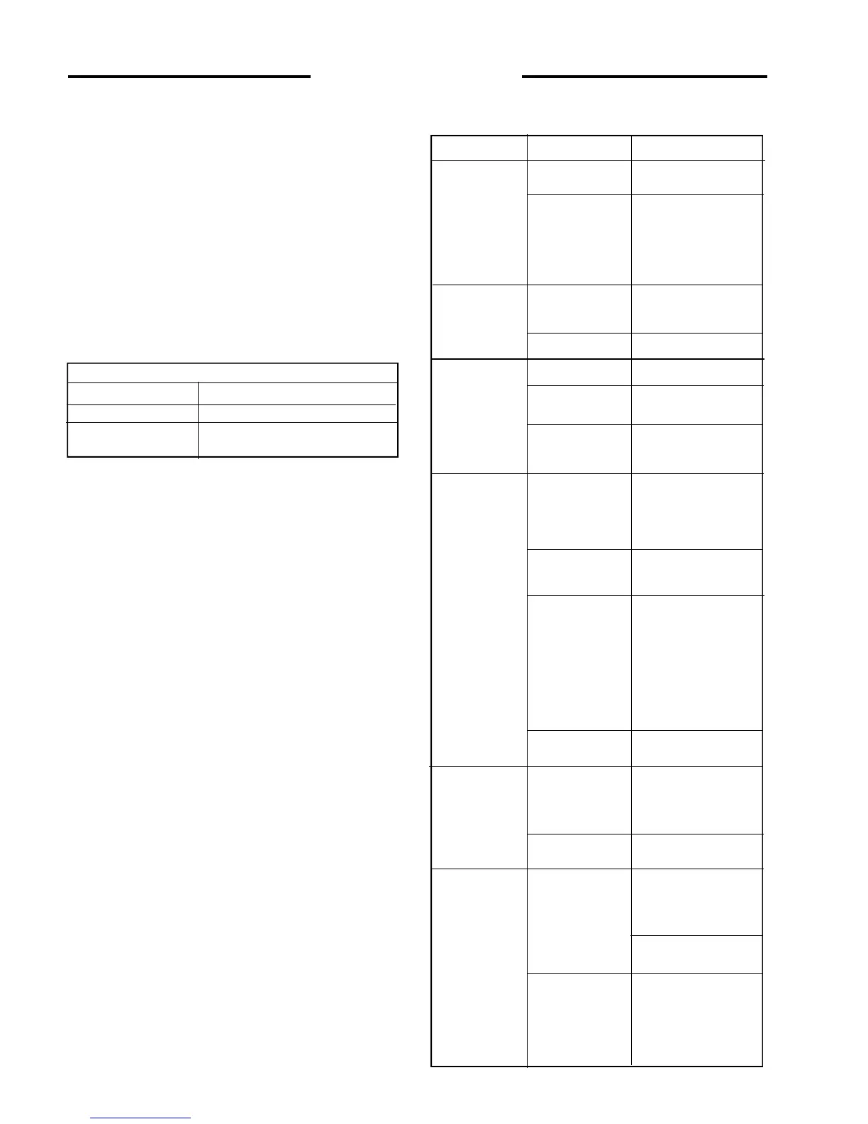
Problem Cause Remedy
• Do not weld, braze, otherwise repair, or use a damaged
rim.
• Never attempt tire repairs on a public road or highway.
• Use jack stands or other suitable blocking to support the
loader while repairing tires.
• Insure jack has adequate capacity to lift your loader.
• Insure jack is placed on a firm level surface.
Do not put any part of your body under the loader or
start the engine while the loader is on the jack.
• Torque lug nuts to specification after reinstalling wheel.
Check lug not torque daily until torque stabilizes.
Tire Inflation Table:
Tire Inflation Pressure
7.00 x 15 50 PSI (345 kPa)
10.00 x 16.5 40 - 45 PSI (276 - 310 kPa)
4. 10B Tire Rotation
The front and rear tires will wear at different rates. For
even wear move the front tires to the rear and the rear tires
to the front when wear is first noticed.
If two tires become worn more than the other two put the
two worn tires on the same side.
When new tires are installed, always keep tires the same
size on the same side of the loader. Two different size tires
on the same side of the loader will cause drive chain wear,
tire wear and a loss of power.
4.11 TROUBLE SHOOTING
4. 11A Electrical System
This machine is equipped with a 12 Volt negative ground
electrical system. The charging system is equipped with
an alternator and built in regulator. The starting circuit is
equipped with a starter motor, glow plugs, and solenoid for
starting the engine.
The seat belt and seat switch are wired in series. In order
to operate the loader, the operator must be sitting in the
seat with the seat belt securely fastened around the waist.
Check battery, charge
or replace
Check for loose or
corroded connectors.
Tighten and clean as
required. Use di-
electric grease to
prevent corrosion.
Check continuity of
cables and replace if
defective
Repair or replace
Check and replace
Check relay continuity
if defective, replace
Check continuity,
repair or replace
Engine will smoke, but
not run unassisted by
starter Disengage
auxiliary hydraulics
See Sect. 2.8 - 2.10.
Check continuity and if
defective replace
Disconnect the ROPS
harness from the
engine harness Fig.
4.10A. Open the dash
panel and check
continuity of the circuit
not functioning
properly in both engine
and ROPS harness
Check fuel level
Defective solenoid or
binding solenoid lock.
Loosen screws and
readjust
Check continuity of
connectors and wire
Defective solenoid or
binding solenoid lock.
Loosen screws and
readjust
Check continuity of
connectors and wire
Check and replace if if
necessary
Battery failure
Battery cable failure
Starter failure
Fuse burnt
Defective relay
Ignition switch
failure
Auxiliary hydraulics
engaged
Defective glow plug
relay
Broken connection
or defective wire
No fuel
Electro solenoids not
releasing valve
spools
Broken or poor
contact from relay to
solenoid on valve
Poor connection in
harness
Engine will not
crank over
Engine cranks
over, will not start
Loader starts, but
foot controls will
not release
Engine will not
stop when the key
is turned OFF
4 MAINTENANCE
Contact Thomas Equipment for all major fixes under the
remedy column except for regular service (i.e. Replenish
fluids, tightening etc.).