15
2 CONTROLS
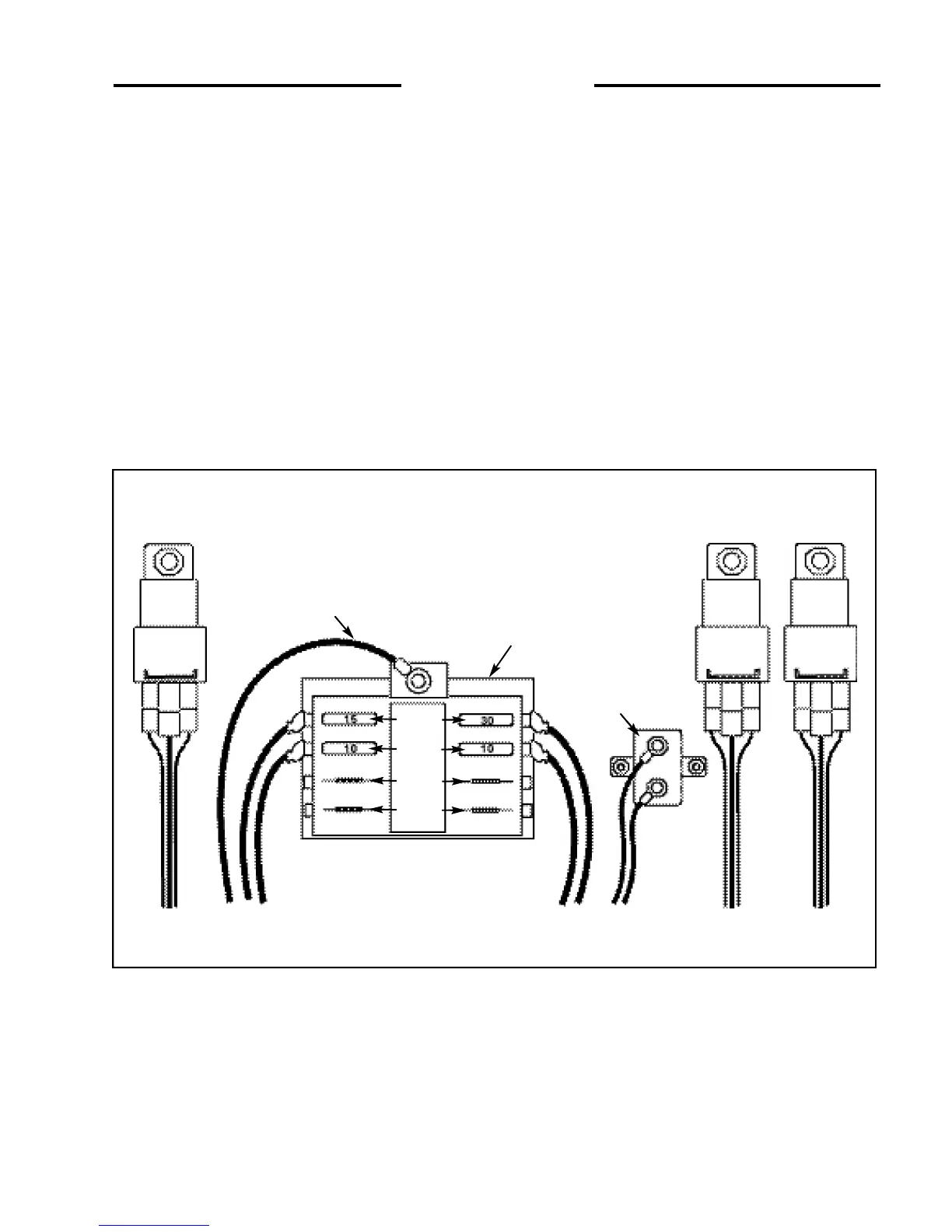
2. 12 ELECTRICAL PANEL
The loader is equipped with a 12 volt, negative ground
electrical system. The fuse and relay panel is located in the
engine compartment just in front of the battery box. The
panel consist of the following:
1. Glow Plug Relay
2. Starter Relay
3. Engine Fuel Stop Timer
4. Fuse Panel
Optional equipment for the loader are back up alarm, horn
and work lights (Fig. 2. 12)
5. Stop Timer (Y/B)
6. Alternator (B/W)
7. Electrical Auxiliary
8. Spare
9. Starter (W/B)
Glow Plug (R/W)
10. Valve Locks (Or/W)
11. Horn
12. Spare
13. From ACC Switch (B/W 12)
14. Circuit Breaker
Fig. 2.12
C3247
Starter Relay
Stop Timer
Glow Plug Relay
13
1
2
3
5
9
14
4
6 10
7 11
8 12