24
Connect the end of the second cable to the negative (–)
terminal of the booster battery. Connect the other end of the
same cable to the engine. Keep cables away from moving
parts. Start the engine. After the engine has started, remove
the ground cable (–) first, then remove the cable from the
boosting lug
3. 11 LOWERING LIFT ARMS
(ENGINE OFF)
In the event that you should have an electrical failure which
renders your skid steer inoperable with the lift arms up, the
following procedures would apply.
3. 11A Lift Arm Height Is Sufficient To Engage
Boom Support Pins
Engage Boom support pins. (Fig. 3.11A) Raise seat bar
and cycle all controls to ensure they are locked. Exit loader
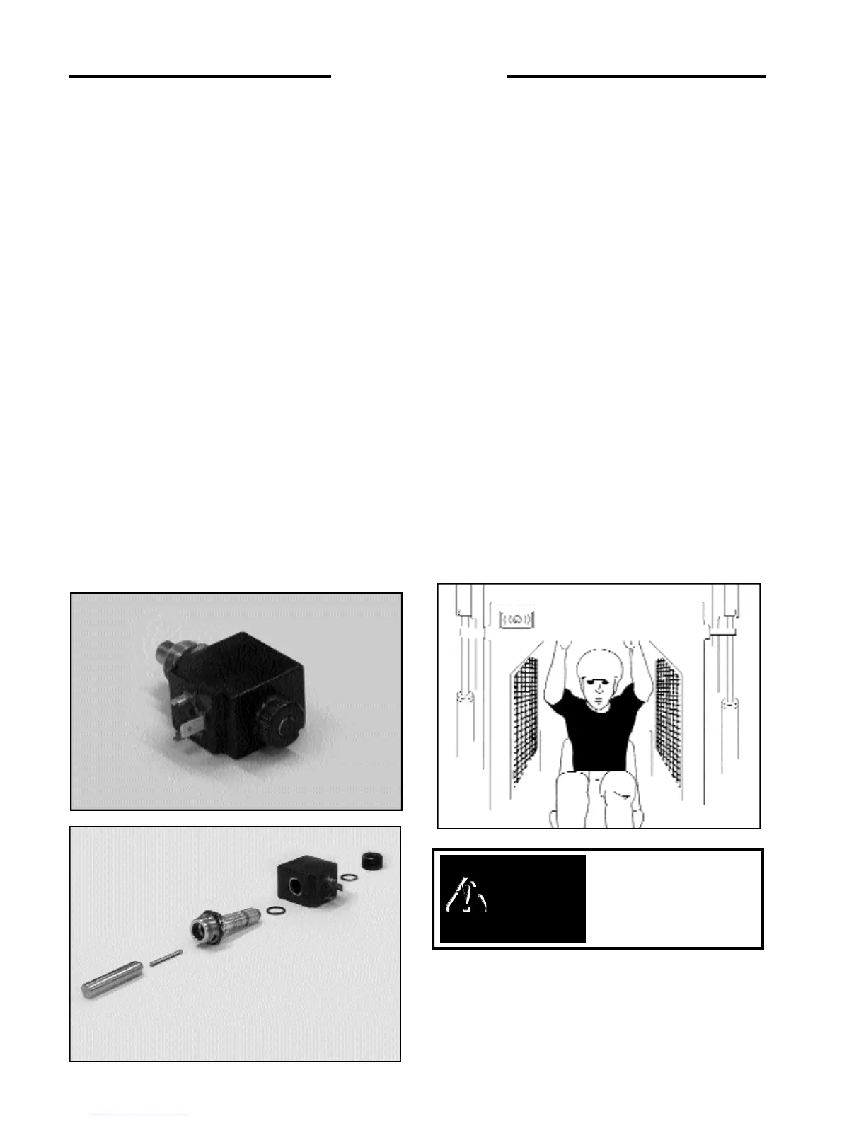
and open rear door. Locate the control valve on the right
side of the machine. Unplug the electrical wire and remove
the knurled nut holding the solenoid on the spool lock
(Fig.3.11A). Remove the solenoid, then remove the lock
pin and spring assy (Fig. 3.11B). Once the lock pin and
spring are removed, the boom spool is free to travel. Enter
the machine, being careful not to cycle the foot pedals or
the control levers as the locking system has been disabled.
Once in the operator seat, lower the safety bar, and dis-
engage boom support pins (Fig.3.11C). Move the boom
pedal or control lever to lower the lift arms to the ground.
3. 11B Lift Arm Height Is Not Sufficient To
Engage Boom Support Pins
DO NOT EXIT FROM FRONT OF LOADER
WITHOUT LIFT-ARMS ON GROUND OR
SUPPORTED BY ACCEPTABLE MEANS!
Raise seat bar and cycle all controls to ensure they are
locked. If help is readily available, have some one place a
suitable support under the boom (i.e. 4” x 4” Lumber) or a
piece of angle iron between lift cylinder end cap and lift
cylinder rod mount. Then exit loader using extreme
caution. If help is not available, the operator must exit the
loader from the rear window and perform the proper lift
arm supporting (As described previously) Once this is
completed, open rear door. Locate the control valve on the
right side of the machine. Unplug the electrical wire and
remove the knurled nut holding the solenoid on the spool
lock (Fig.3.11A). Remove the solenoid, then remove the
lock pin and spring assy (Fig. 3.11B). Once the lock pin
and spring are removed, the boom spool is free to travel.
Ensure assistance is available, then the operator can enter
the machine, being careful not to cycle the foot pedals or
the control levers as the locking system has been disabled.
Once in the operator seat, lower the safety bar. Have the
assistant remove the lift arm support devices. The operator
can then move the boom pedal or control lever to lower the
lift arms to the ground.
Fig. 3.11C
3 OPERATION
To avoid personal injury:
Do not leave boom arms
up unless the boom locks
are engaged.
WARNING
C730
Fig. 3.11BC3243
Fig. 3.11A
C3244