MEC 2 MICROPROCESSOR ENGINE/GENERATOR CONTROLLER
PM056 Rev 6 05/10/15 Thomson Technology
10
The MEC 2 controller can be installed onto a door of a control panel using one of the
following methods:
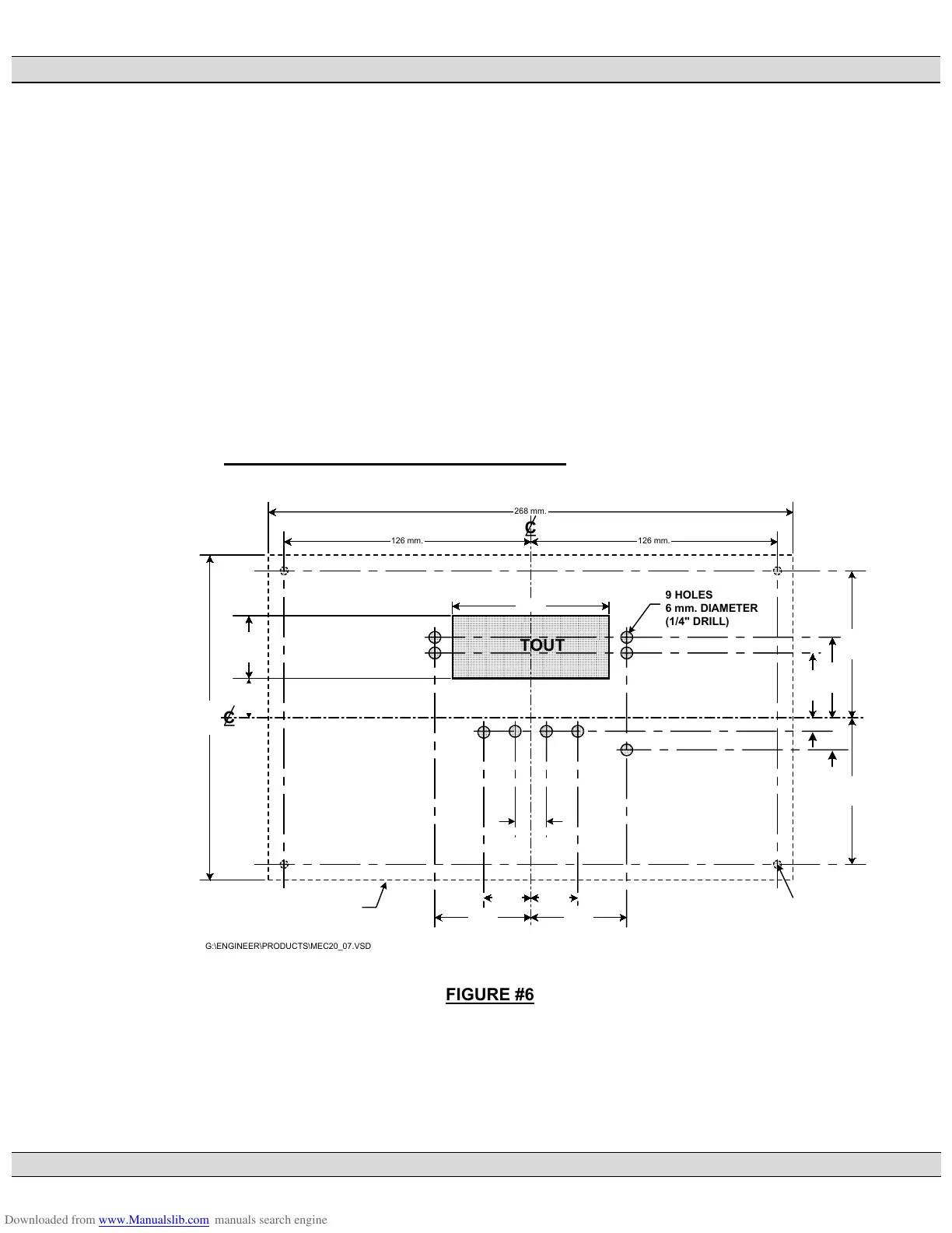
• The first method requires a special door cutout for the LCD display and LED’s
as shown in FIGURE #6. This mounting method requires the lexan faceplate
to be mounted directly onto the door of the control panel. The controller must
be disassembled to mount on the door, then re-assembled. Refer to FIGURE
#7 for correct assembly location of all parts.
• The second method of controller mounting requires a factory supplied
adapter faceplate as shown in FIGURE #8. This method only requires a
single large rectangular hole to be cut out of the door as shown in FIGURE
#9.
2.11. FACEPLATE MOUNTING DIMENSIONS
268 mm.
126 mm.126 mm.
166 mm.
49 mm.49 mm.
24 mm.24 mm.
75 mm.75 mm.
OUTLINE OF PRINTED CIRCUIT
BOARD UNDER PANEL DOOR
4 HOLES
4 mm. DIAMETER
(3/16" DRILL)
33 mm.
41 mm.
7 mm.
16.5 mm.
20 mm. 32 mm.
80 mm.
8 mm.8 mm.
TOP
CUTOUT
9 HOLES
6 mm. DIAMETER
(1/4" DRILL)
C
C
G:\ENGINEER\PRODUCTS\MEC20_07.VSD
FIGURE #6
 Loading...


