13
EN
EN
COLOUR VIDEO INTERCOM
C - INSTALLATION
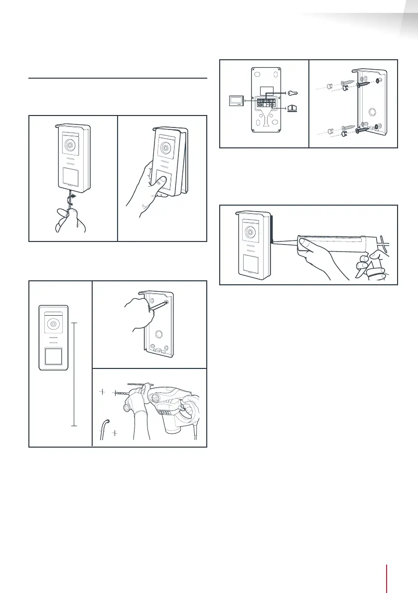
5. INSTALLATION OF THE MAIN OR ADDITIONAL
INTERCOM PANEL
Note: The product must not be connected to the
power supply before the wiring has been completed.
• Remove the tamper-resistant screw under the
intercom panel.
• Tilt the intercom panel forwards.
1.60m
• The lens of the intercom panel must be placed at
a height around 1.60m.
• Make guiding marks.
• Drill. Use wall plugs suitable for the nature of the
material (the wall plugs provided are suitable for
solid walls).
GND
• Connect the two wires from the monitor and if
necessary, connect the electric strike plate and
the gate (see Section 1. Wiring).
• Check proper functioning (video call, etc.).
• Place a silicone* seal between the shield and the
wall to avoid the inltration of water. * Do not
use an acetic acid-based silicone (smells like
vinegar). It is not recommended to run a silicone
seal under the intercom panel