2.0 YOUR RECEIVER
2.1 DEFAULT PIN: 1234
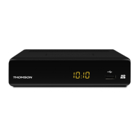
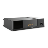
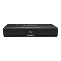
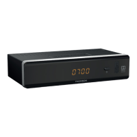
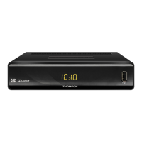
2.2 Front Panel
Fig. 1
1. IR sensor Point your remote control towards this sensor.
2. 4 digits display: Indicates current time in STANDBY mode
Indicates current channel number in OPERATING mode
3. Mode indicator RED indicates that the receiver is in STANDBY mode.
GREEN indicates that the receiver is in OPERATING mode.
4. USB Connector for USB storage devices.
2.3 Rear Panel
Fig. 2
1. ANT IN To connect to your antenna for reception of broadcasted signals.
2. ANT OUT To connect the terrestrial antenna signal to your TV set. This
connection will allow you to watch digital terrestrial programmes
depending on the tuner of your TV and local broadcast
conditions
3. S / PDIF Coaxial: To connect your receiver to a digital home theatre, AV receiver or
digital audio amplifier.
4. HDMI To connect your receiver with your TV set using an HDMI cable.
5. TV SCART To connect your receiver with your TV set using a SCART cable.
6. Audio L/R To connect your receiver to an analogue audio amplifier.
7. Power cord Your receiver requires a supply voltage of 220 – 240 V AC
(Auto-selectable), 50/60Hz ±5%. Please ensure the local power
specification meets these requirements before connecting your
receiver to the wall outlet.
2.4 Remote control
Fig. 3
1. q Switches the receiver On/Standby
2. Mutes all audio outputs of the receiver
3. PG+/PG- Page up/down in all list modes
4. DTV/VCR No function
5. INFO Opens the current channel information; 2x opens the current
event information and 3x the signal information
6. VOL+/VOL- Increases/decreases the volume level
7. MENU Opens the main menu, in a menu you will get one step back
8. EXIT Exits from the menu or sub-menu
9. pq Menu Off: Change channel to next/previous.
Menu On: Moves the cursor up/down.