OPERATING MANUAL 7. MAINTENANCE
ThyssenKrupp Aufzugswerke GmbH
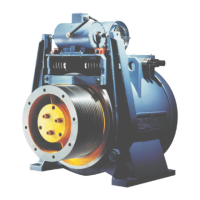
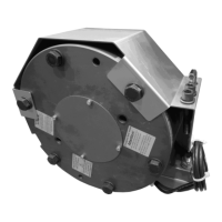
7.5 Replacing of traction sheave
Disassembly:
• Switch off power supply, secure car and counterweight
• Remove traction sheave cover and/or rope fixing beam
• Remove load from traction sheave by discarding ropes
• Secure traction sheave with hoist
• Measure and note down measure of tensioned brake springs
• Remove load from tensioning springs until traction sheave is free by
unscrewing the screws
• Unscrew rope fixing beam
• Unscrew disk on motor shaft and turn disk of motor shaft once
(the side of the disc recess shall be visible)
• Unscrew screws in outer
hole circle of disk and screw them in traction
sheave hub
• Remove traction sheave from shaft by tightening the screws uniformly
and alternately.
Place a spacer, 2 to 6 mm thick, under disk and shaft end if the take off
distance is insufficient.
Assembly:
• Clean shaft end and drilled hole of traction sheave; never make any
dimensional changes in featherkey, groove, shaft or drilled holes.
• Do not grease or oil shaft or drilled hole.
• Carefully fit new traction sheave to conical shaft end of motor shaft.
• Bring position of featherkey and groove in line.
• Slide traction sheave on motor shaft, note position of brake shoes !
• Screw disk in inner hole circle of motor shaft. The recess side shall be in
line with the traction sheave.
• Secure screws against unintentional unscrewing by means of Loctite type
241 and tighten them alternately and uniformly clock-wise. This requires
several operations.
• Check that brake linings and brake disk surface are aligned laterally. In
the case of mismatch dismount brake shoes, re-arrange spacers on
brake shoe bearings and bring brake linings and brake disk centre in line.
(disk thickness = 1 mm)
• Adjust pressure force of springs, brake shoe stroke 0.3 mm and brake
test switch.
• Mount traction sheave cover and/or rope fixing beam.
Attention : if the traction sheave is assembled incorrectly it can work loose.
See to it that screws are tightened and check tightening torque !
See table 9.1 in annex.