OPERATING MANUAL 1. SAFETY
ThyssenKrupp Aufzugswerke GmbH
1.3 Emergency operation ″
″″
″release after safety gear
operation″
″″
″
If safety gear operation is effected on car or counterweight side the traction of
the traction sheave may be insufficient for moving the car, the ropes may slip.
The following measures are necessary:
• Disconnect drive and control.
• Remove traction sheave cover and/or rope fixing beam above traction
sheave.
• Place hydraulic jack in location hole of machine frame on tension side of
lowered traction sheave.
• Bolt pressure arm with centering pin down to end face of traction sheave.
Use thread close to jack (see fig. 2)
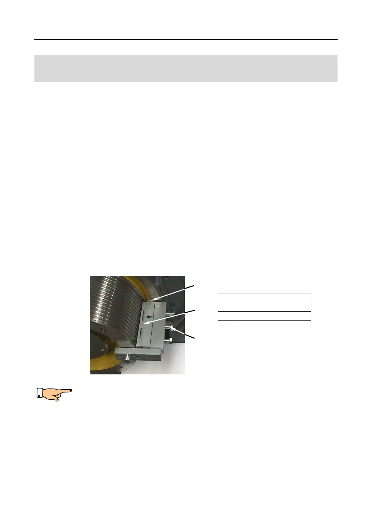
• Nest nib of blocking clamp in snap ring groove below the brake disk and
screw to traction sheave in next thread above thrust piece (see fig. 1).
• Tighten 3 pressure screws and clamp ropes by means of thrust piece.
• Operate brake release lever on brake magnet and move traction sheave
into desired direction until the grip wedge is released by pushing the lever
upwards and downwards. (See to it that the drain valve is closed and the
centering pin of the thrust piece shall rest on the groove of the lever).
• Remove the blocking clamp and install the rope fixing bracket in
accordance with the instructions after disengagement.
Installation of blocking clamp
Note: if the travel of the hydraulic jack or the travel of the traction sheave is
not enough for releasing the car, it shall be maintained in its position with the
rope clamp. The recess of the rope clamp shall rest on the machine frame
and the other rope clamp side on the welded-on bracket on the inside of the
frame.
Lower hydraulic jack, re-adjust thrust piece on next fastening thread on
traction sheave above hydraulic jack. Re-adjust blocking clamp if the travel is
insufficient.
Fig. 1
1
Nib
2 Thrust piece
3 Pressure screw
1
2
3