OPERATING MANUAL 7. MAINTENANCE
ThyssenKrupp Aufzugswerke GmbH
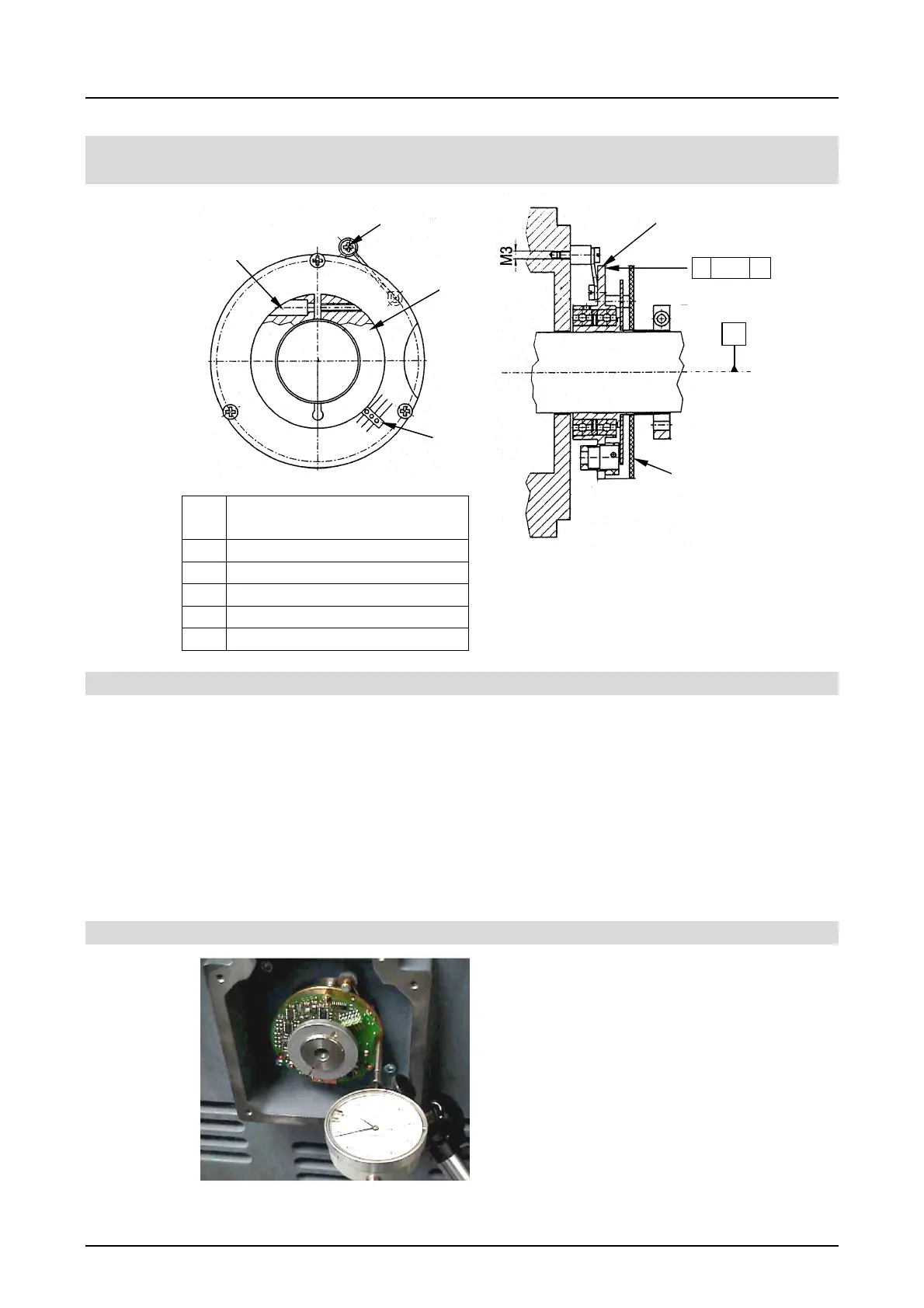
7.6 Replacing of pulse generator
Disassembly:
• Remove cover at rear bearing bracket of machine.
• Remove connector plug on generator board (printed circuit board)
• Unscrew rotary support screw M3
• Unscrew locking screw on straining ring by means of hexagon socket
screw M2.5
• Grasp generator on bearing flange and carefully remove from shaft end
In the case of SA1 (2. generator) disassemble and remove 2. generator in
the same way.
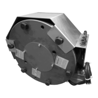
Assembly:
For mounting the generator a dial
gauge with indiator accurate to 0.01
mm incl. magnet holder is necessary.
• Clean but do not grease shaft prior to
mounting. Shaft end shall be clean
and not greasy.
• Check true running of shaft journal
and bearing flange by means of dial
gauge (max. radial run-out 0.03 mm)
1
4
3
2
1 Drilled hole for locking
screw
2 Rotary support screw
3 Straining ring
4 Connection terminals
5 Bearing flange
6 Generator board
Fig. 16
Fig. 15
Technical data see 2.8
5
1
0.03