External Output Specifications
■USB output method
・Preparation (PC)
①Install a communication driver in the USB responsive PC.
(Download the communication driver from the Tohnichi Mfg. Co., Ltd. website.)
②Set the PC ports and communication format.
(For the installation method and communication setting, see the downloaded operating instruction.)
・Preparation (STC2-G)
③Turn on the STC2-G
④
Make the baud rate, data length and parity settings consistent with the settings of the PC.
・Communication
⑤Connect a USB cable (accessory) to the PC and the STC2-G.
⑥Start communication software. (Option)
・Data output
⑦Data output method (See Measurement Data Batch Output.)
NOTE)・Use the accessory USB cable to connect to the PC.
・
Communication may not be enabled unless software is started up after connecting the cable.
・Communication is disabled if multiple units of the STC2-G and our USB serial output
products (CEM3-G, ST2, ATGE-G) are connected to the PC simultaneously.
,
Hardware(RTS/CTS)
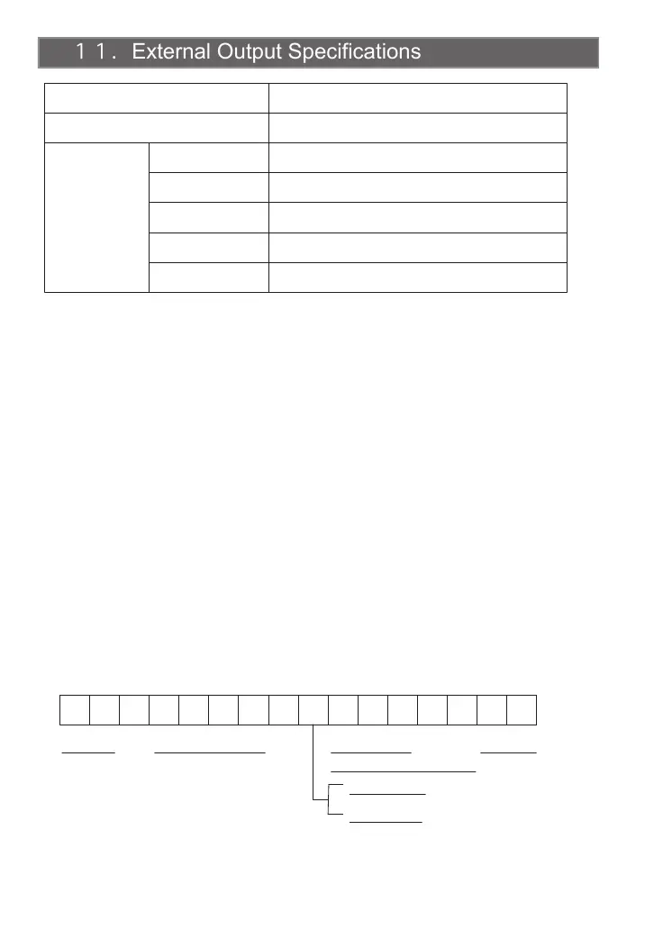
■Output format
R E , 0 1 0 0 , - 1 0 0 . 0 CR LF
NOTE)
Measurement is disabled while the USB cable is connected.
12
USB Interface
Connector
Serial
Interface
Baud rate
Data length
Stop bit
Parity
Flow control
None, even number, odd number (Default: None)
1 bit
7 bits/8 bits (Default: 7 bits)
2400, 4800, 9600, 19200 bps (Default: 2400 bps)
USB mini B
Compliant with USB 2.0 (USB-serial conversion chip used)
Header
Memory counter (4 digits)
Torque value
(Including decimal point)
CW: Blank
CCW: “ - ”
Delimiter
※Note: Prior to STC2 software version 1.4, flow control: None.
(Version infoemation is displayed by an LCD screen when reset it. See page 14 Reset Operation.)