− 38 −
R-CL300-0-1204-02
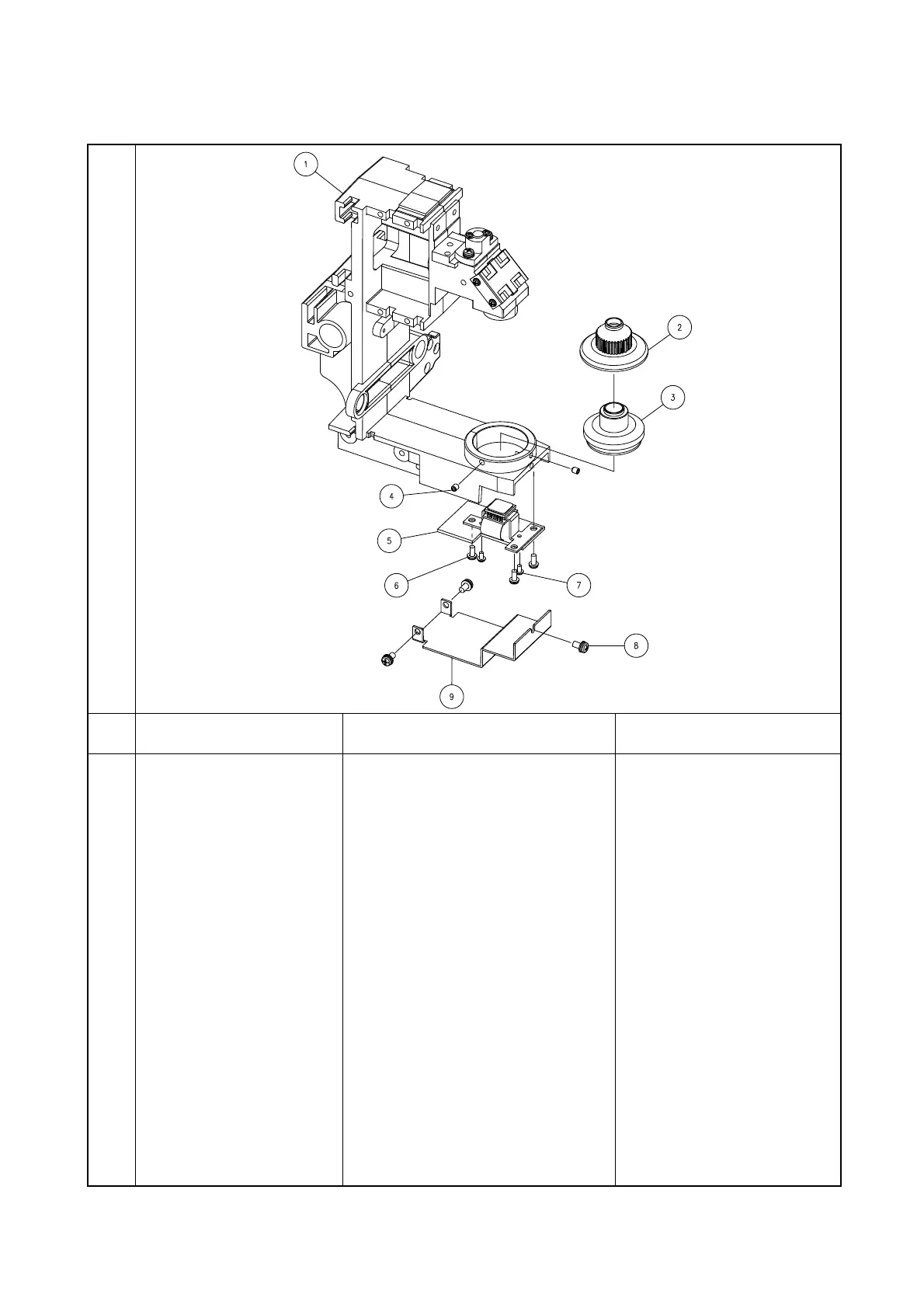
3-4-8 CCD/CCD PCB Assembly Removal
Illustration
Proc. Disassembly Removal method Point for assembly
1 Target Unit (3) Removal • Peel off the dust preventive tape
adhering the CCD cover (9) onto the
measuring unit (1).
• Remove the holder (2).
• Remove the two screws (4) and
remove the target unit (3).
Assemble the unit using the
reverse procedure for
disassembling.
2 CCD Cover (9) Removal • Remove the three screws (8).
• Remove the CCD cover (9).
3 CCD/CCD PCB Assembly
(5) Removal
• Disconnect the CCD cable.
• Remove the three screws (6) and
two screws (7).
• Remove the CCD/CCD PCB
Assembly (5).
After you have removed the
CCD unit or target frame, a
message is displayed at the
system startup. Access
“FACTORY MENU” by the
input method mentioned in
“3-1 FACTORY MENU” and
adjust the position with “CCD
POSITION”. Then, it is
necessary to perform all the
corrections on and after “SELF
CHECK”.
 Loading...