− 44 −
R-CL300-0-1204-02
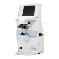
3-6-8 PRINTER PCB Change
(1) Remove the port, left and right covers. (Refer to P.31.)
(2) Disconnect the cable from the CPU PCB.
(3) Disassemble the PRINTER unit. (Refer to P.34.)
(4) Remove the PRINTER PCB FPC (flexible pattern circuit).
(5) Remove the PRINTER PCB FPC. Disconnect the PRINTER cable.
(6) Change the PRINTER PCB.
(7) Connect the PRINTER FPC of the PRINTER PCB. Connect the PRINTER cable.
(8) Connect the PRINTER FPC of the PRINTER PCB.
(9) Attach the PRINTER unit onto the PRINTER base.
(10) Connect the PRINTER cable to the CPU PCB.
(11) Attach the port, left and right covers.
3-6-9 Communication Cable Malfunction Check
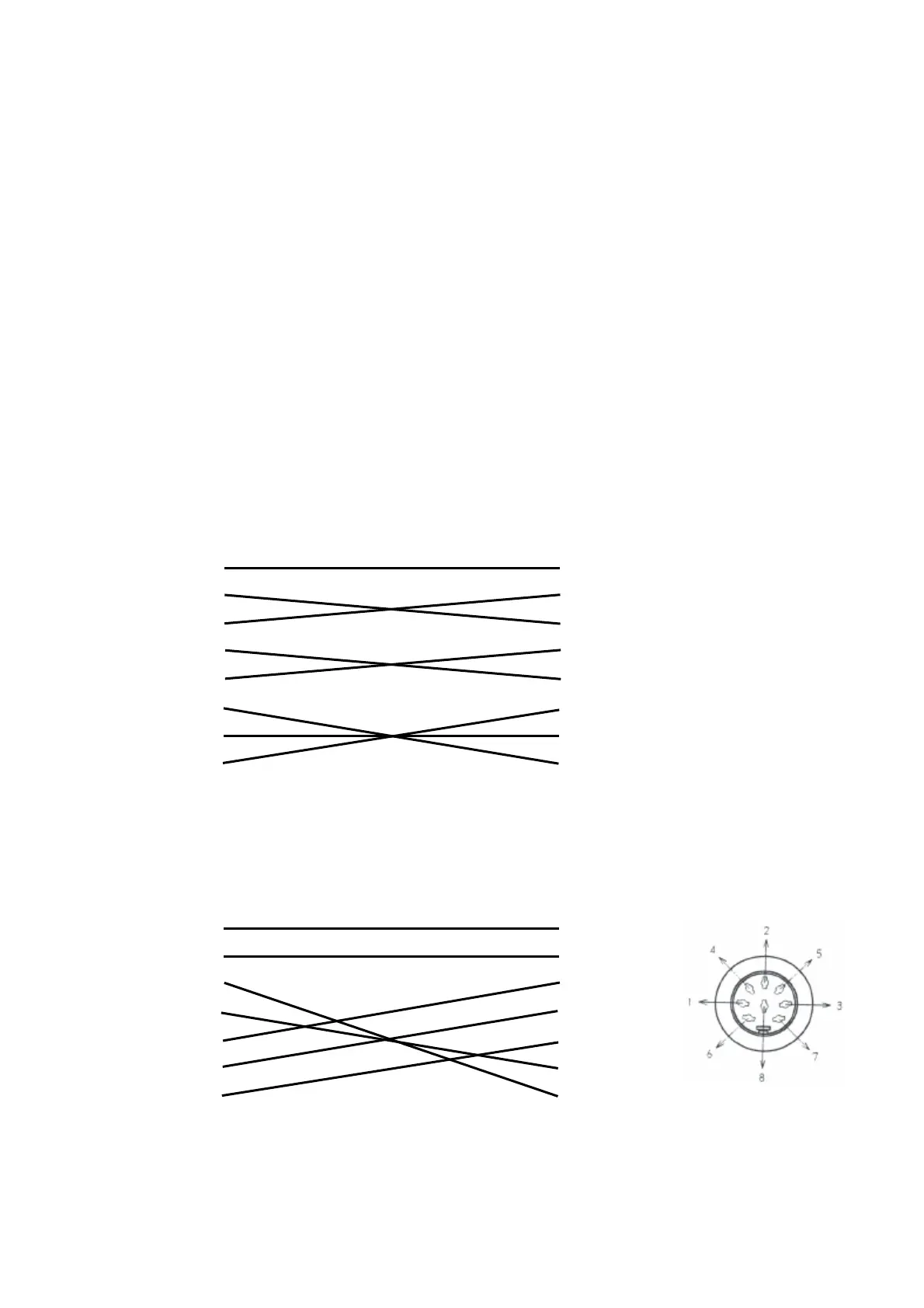
(1) Connection of CL-300 and NEC PC98 series
Instrument (DIP8 pins) Personal Computer (D-SUB 25 pins)
FG 1 1 FG
SD 2 2 SD
RD 3 3 RD
RTS 4 4 RTS
CTS 5 5 CTS
DSR 6 6 DSR
SG 7 7 SG
DTR 8 20 DTR
(2) Connection of CL-300 and IBM PC DOS/V
Instrument (DIP8 pins) Personal Computer (D-SUB 9 pins)
FG 1 1 FG
SD 2 2 SD
RD 3 3 RD
RTS 4 4 RTS
CTS 5 5 CTS
DSR 6 6 DSR
SG 7 7 SG
DTR 8 8 DTR
Make sure that the connection is as shown above with the tester.
 Loading...