− 3 −
R-CL300-0-1204-02
1-5 Precautions
(1) Even when two or more malfunctions are found, make sure to check the product according to the flow
chart.
(2) Make sure to turn OFF the power before the connector or PCB is replaced.
(3) In the case of a failure of the electric system, basically replace the PCB unit.
Replaceable PCBs Part No.
1. CPU PCB
2. CCD PCB
3. I/O PCB
4. I/O PCB (with LAN)
5. PRINTER PCB
6. MEMORY PCB
7. POWER SW PCB
42028 7100
42028 7200
42028 7300
42028 7350
42028 7400
42028 7500
42028 7600
When the CPU PCB is replaced, it is necessary to check with the “FACTORY MENU”, to correct the
accuracy in each item and to set the parameters in “INITIAL MENU”.
When the CCD PCB is replaced, it is necessary to position the CCD using the “CCD POSITION” function in
the “FACTORY MENU” and to correct the accuracy in each item.
When the CCD PCB is to be replaced, be careful about scratch, dust or dirt on the CCD.
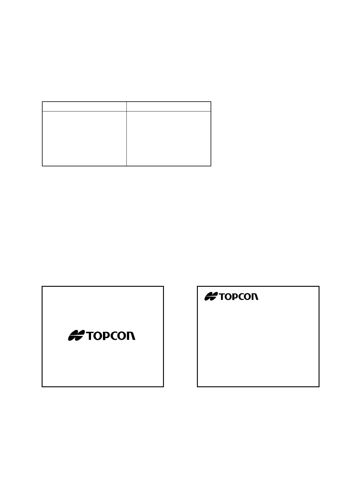
1-6 ROM Version Display
Usually, when the power to the instrument is turned ON, the “TOPCON” logo mark is displayed first, and
then the following image is displayed.
The bottom line shows the ROM version No. and in this example, the version No. is “1.00.00”.
Note:
When the CPU PCB has been replaced, this image is not displayed even when the power switch is
turned ON, but “NO CORRECT” is displayed. In this case, refer to “3-1 FACTORY MENU”.
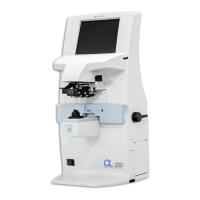
CL
-
300
COMPUTERIZED LENSMETER
Ver1.00.00
 Loading...