− 44 −
3-6-2 Correction of the spherical unit zero position
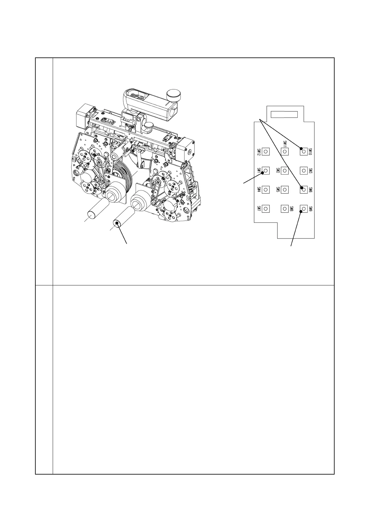
Illustration
Procedure
1. Install the lens zero positioning tool to the dowel of the metal plate.
2. Set the proper DIP SW of the MAIN PCB to “ON” for the lens to be corrected. (Refer to the
attached paper.)
3. Install the tool PCB to the MAIN PCB.
4. As pressing SW9 of the tool PCB, turn on the power.
(When turning on the power, do not insert the lens zero positioning tool.)
5. Press SW10 and SW6 of the tool PCB to correct the zero position.
6. As pressing SW12 of the tool PCB, press SW4. (The correction value is written.)
7. After writing, perform the zero detection with SW1 to check if the lens zero positioning tool
is inserted.
Zero position correction
(SW6/SW10)
Lens zero positioning tool